Table of Contents
Advertisement
Advertisement
Table of Contents

Subscribe to Our Youtube Channel
Related Manuals for PASCO Basic Electrostatics System


Summary of Contents for PASCO Basic Electrostatics System
- Page 1 Instruction Manual 012-07227G *012-07227* Basic Electrostatics System ES-9080A...
-
Page 2: Table Of Contents
Basic Electrostatics System 012-07227G ES-9080A Table of Contents Equipment List....................3 Introduction....................4 Equipment Description ................5 - 10 Electrometer ...........................5 Electrostatics Voltage Source ......................6 Variable Capacitor .........................7 Charge Producers and Proof Plane....................7 Faraday Ice Pail..........................9 Conductive Spheres........................10 Conductive Shapes........................10 Electrometer Operation and Setup Requirements ........ -
Page 3: Equipment List
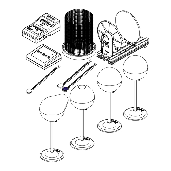
ES-9080A 012-07227G Basic Electrostatics System Basic Electrostatics System ES-9080A Equipment List Included Equipment Model Number* 1. Basic Electrometer (cables not shown) ES-9078A 2. Electrostatics Voltage Source (cable and AC adapter not shown) ES-9077 3. Basic Variable Capacitor (cable not shown) ES-9079 4. -
Page 4: Introduction
Moreover, the traditional demonstrations usually gave qualitative rather than quantitative results. PASCO has attempted to remedy this by designing the complete ES- 9080A Basic Electrostatics system. This guide will give the instructor enough of a step-by- step explanation to master demonstration techniques. The range of demonstrations in this guide more than covers the material usually presented in an undergraduate unit on electrostatics. -
Page 5: Equipment Description
ES-9080A 012-07227G Basic Electrostatics System day can cause charge to easily build up in any moving object, including people. Minimize all movement when demonstrating on a very dry day. • Practice - Nothing can ruin the instructive value of a demonstration more than failure due to a demonstrator’s unfamiliarity with the equipment and procedure. -
Page 6: Electrostatics Voltage Source
Basic Electrostatics System ES-9080A With these features, you’ll find that your electrostatics demonstrations and labs are easier to perform and, with quantitative data, are more informative. meter display zero button, ground and remove excess charge output for interface (not shown) -
Page 7: Variable Capacitor
Charge Producers and Proof Plane (ES-9057B) The Charge Producers and the Proof Plane are Non-conductive neck electrostatic components for use with the PASCO Electrostatic System. The charge producers are used to Handle generate charges by contact. The proof plane is used to measure charge density on a charged surface. - Page 8 Basic Electrostatics System ES-9080A • Avoid touching the neck during normal use. The oils from your hands will provide a path for charges to leak off. If you experience a lot of leakage, wash the white non-conductive neck with soap and water, rinsing generously; the leakage should disappear. Occasionally clean the disk surfaces with alcohol.
-
Page 9: Faraday Ice Pail
Use the conductive knob on the end of the proof plane to sample the charge density inside a hollow sphere (such as ES-9061 Conductive Shapes). Faraday Ice Pail (ES-9042A) The PASCO Faraday Ice Pail is shown in Figure 8. Originally designed by Michael Faraday, it works on the Shield... -
Page 10: Conductive Spheres
Basic Electrostatics System ES-9080A To prevent stray charges from producing erroneous results, it is extremely important that the Faraday Ice Pail be momentarily grounded prior to starting any experiment. The demonstrator must also be continually grounded while performing an experiment. -
Page 11: Electrometer Operation And Setup Requirements
ES-9080A 012-07227G Basic Electrostatics System NOTE: When handling the conductive shapes, take care to keep each shape and non- conductive rod free of dirt, grease, and fingerprints to minimize leakage of charge from the shapes. Five binding posts allow the voltage source and/or the electrometer to be connected to components. - Page 12 Basic Electrostatics System ES-9080A 5. Use the push button to set the voltage to the desired range. The range setting refers to the voltage input required to produce a full-scale meter deflection (e.g., a setting of 30 means that a full-scale meter deflection indicates a voltage of 30 volts).
-
Page 13: Suggested Demonstrations
ES-9080A 012-07227G Basic Electrostatics System Demonstration 1: Faraday Ice Pail and Charge Production Equipment Required: Electrometer (ES-9078A) Faraday Ice Pail (ES-9042A) Charge Producers (ES-9057B) Signal Input Cable (test leads) Earth ground connection Proof plane (optional) Suggestions for Introducing the Experiment Start by showing that the electrometer is directly measuring potential difference by connecting a battery to it and measuring its voltage. - Page 14 Basic Electrostatics System ES-9080A Before beginning any experiment using the ice pail, the pail must be momentarily grounded. When the ice pail is connected to the electrometer, and the electrometer is connected to an earth-ground, simply press the ZERO button whenever you need to discharge both the pail and the electrometer.
- Page 15 ES-9080A 012-07227G Basic Electrostatics System • Before inserting the charged disk in the ice pail, make sure you’re touching the grounded shield. 4. Carefully insert the charged object into the ice pail, all the way to the lower half of the pail, but without letting it touch the pail.
- Page 16 Basic Electrostatics System ES-9080A 5. Remove one charge producer and note the electrometer reading. Replace the charge producer and remove the other. Note the electrometer readings. Using the magnitude and polarity of the measurements, comment on conservation of charge. Extra Things to Try 1.
-
Page 17: Demonstration 2: Charge Distribution
ES-9080A 012-07227G Basic Electrostatics System Demonstration 2: Charge Distribution Equipment Required: Electrometer (ES-9078A) Faraday Ice Pail (ES-9042A) Electrostatic Voltage Source (ES-9077) Proof Plane Conductive Spheres, 13 cm (ES-9059B) (2) Signal Input cable (Test leads) Earth ground connection (patch cord) Conductive Shapes (ES-9061) - Page 18 Basic Electrostatics System ES-9080A However, by not grounding the proof plane (and by not letting it touch the ice pail), the charge on the surface is not depleted. That charge which the proof plane removed for one measurement is always returned to the surface when the next sampling is made.
- Page 19 ES-9080A 012-07227G Basic Electrostatics System Conductive Conical Shape 1. Remove the two conducting spheres. Connect the conductive conical shape to the +2000 VDC port on the Electrostatics Proof Voltage Source. plane 2. Use the proof plane to sample charge at the larger rounded end and then at the narrow end.
- Page 20 Basic Electrostatics System ES-9080A ®...
-
Page 21: Demonstration 3: Capacitance And Dielectrics
ES-9080A 012-07227G Basic Electrostatics System Demonstration 3: Capacitance and Dielectrics Equipment Required: Electrometer (ES-9078A) Faraday Ice Pail (ES-9042A)l Charge Producers (ES-9057B) Proof Planes (ES-9057B) Electrostatic Voltage Source (ES-9077) Signal Input cable (Test leads) 13 cm Conductive Spheres (2) (ES-9059B) Variable Capacitor (ES-9042A) - Page 22 C, V, and Q for the parallel plate capacitor. Values read by the electrometer are to be used as relative, comparative measurements. The electrometer can be connected to a computer and used with a PASCO interface to obtain a graphical display of information. 3B.1: V Measured, Q Variable, C Constant 1.
- Page 23 ES-9080A 012-07227G Basic Electrostatics System voltage source. Take care to place the capacitor sufficiently far away from the sphere and the voltage source, to prevent it from being charged by induction. Electrometer To AC power adapter Electrostatics Voltage Source Figure 3.2: Demonstration Setup 2.
- Page 24 Basic Electrostatics System ES-9080A 5. Double the plate separation to 4 mm and repeat the procedure. What happens to the potential now? Compare the values to the previous case. Alligator clip To AC power adapter Figure 3.3a: Demonstration Setup 3B.2: Q Measured, C Variable, V Constant 1.
- Page 25 ES-9080A 012-07227G Basic Electrostatics System port on the voltage source. The Faraday Ice Pail is connected to the electrometer and the electrometer is grounded to earth (i.e., through the COM port on the voltage source.). To AC power adapter Figure 3.3b: Demonstration Setup 2.
- Page 26 Basic Electrostatics System ES-9080A 3B.4: V Measured, C Variable, Q Constant 1. Figure 3.4 shows the equipment set up. The Variable Capacitor is connected to the electrometer and the electrometer is grounded to earth (through the COM port on the voltage source).
- Page 27 ES-9080A 012-07227G Basic Electrostatics System The ideal procedure to measure would be to simply slip a piece of dielectric material between a set of charged capacitor plates and then note the changes in potential. However, sliding a dielectric between the plates of the capacitor when they are too close together can generate a significant static charge that will alter the measurements.
- Page 28 Basic Electrostatics System ES-9080A 5. After inserting the dielectric, return the plates to the original 3 mm separation and record the new electrometer reading, V 6. Pull the plates apart again, and lift and carefully remove the dielectric sheet. 7. Return the plates to the original 3 mm separation and check that the electrometer reading agrees with the original V reading.
- Page 29 ES-9080A 012-07227G Basic Electrostatics System After some algebra and rearranging, you find that – ------- ------------------------------------------- - where the ratio C´ is the dielectric coefficient ----------- ------- Table 3.1: Some Dielectric Coefficients ...
- Page 30 Basic Electrostatics System ES-9080A 3D.1: Capacitors in Series Make sure all capacitors are uncharged before connecting them. (Use a short wire to momentarily short each one.) 1. Set up the series circuit, as shown in Figure 3.7a. 2. Plug in to the 30 VDC output on the Voltage Source. Close switch A to charge capacitor 3.
-
Page 31: Demonstration 4: Charging And Discharging Capacitors
Use lower resistances (100-1000 for this method. Equipment Setup The signal output cable of the electrometer allows it to be connected to a PASCO interface as an analog sensor. 1. Open the software program and select the electrometer from the list of sensors. - Page 32 2. Set up the circuit shown in Figure 4.1, where the resistor and the capacitor are connected in series to the voltage source, set at 30 VDC. The electrometer output goes to one of the analog channels of the PASCO interface . Use a single-pole double-throw switch. signal output...
- Page 33 Figure 4.3: Experimental Setup Experimental Setup 1. Set up the circuit shown in Figure 4.3, where the resistor and the capacitor are connected in series to the signal output generator of the PASCO 750 Interface. Use a 200 F capacitor and ®...
- Page 34 1000 he electrometer is reading the voltage across the capacitor, and it is also connected to one of the analog channels of the PASCO interface. 2. With the DataStudio software, create a display of voltage vs. time for the readings of the electrometer.
-
Page 35: Technical Support, Copyright And Warranty Information
PASCO scientific warrants the product to be free from defects in materials and workmanship for a period of one year from the date of shipment to the customer. PASCO will repair or replace, at its option, any part of the product which is deemed to be defective in material or workmanship. -
Page 36: Product End Of Life Disposal Instructions
Basic Electrostatics System ES-9080A Product End of Life Disposal Instructions: This electronic product is subject to disposal and recycling regulations that vary by country and region. It is your responsibility to recycle your electronic equipment per your local environmental laws and regulations to ensure that it will be recycled in a manner that protects human health and the environment.
Need help?
Do you have a question about the Basic Electrostatics System and is the answer not in the manual?
Questions and answers