Table of Contents
Advertisement
Quick Links
WSC 310 & WSC 320
(Version 1711 – from firmware version 1.26 (main card) &
Save this installation instruction to the end user
+44 (0) 1536 614 070
UK
+45 4567 0300
Other markets
WSC 3xx iinstall 1711-Firmware v126 - UK
WindowMaster International A/S, Skelstedet 13, DK-2950 Vedbæk
Plus versions
Installation instruction
CompactSmoke
from version 1.06 (motor line card))
Info.uk@windowmaster.com
Info.dk@windowmaster.com
©WindowMaster 2015, 2017 ®WindowMaster is a registred trademark used under the license by WindowMaster International A/S
™
www.windowmaster.com
Advertisement
Table of Contents

Related Manuals for Window Master CompactSmoke WSC 310

Summary of Contents for Window Master CompactSmoke WSC 310
- Page 1 WSC 310 & WSC 320 Plus versions Installation instruction ™ CompactSmoke (Version 1711 – from firmware version 1.26 (main card) & from version 1.06 (motor line card)) Save this installation instruction to the end user +44 (0) 1536 614 070 Info.uk@windowmaster.com +45 4567 0300 Other markets...
-
Page 2: Table Of Contents
1 Safety information ................................ 4 Safety ................................4 230V AC ................................4 Back-up batteries .............................. 4 Application ................................. 4 Cable routing and electrical connection ......................4 2 Structure of the smoke panel ............................5 3 Variants of panels ................................ 6 CompactSmoke™... - Page 3 14.17 Fieldbus (KNX and BACnet) ..........................51 14.17.1 KNX configuration ............................51 14.17.2 BACnet configuration ..........................52 15 Status – main menu ..............................52 16 Manual operation – main menu ..........................52 17 Configuration missing – main menu ........................53 18 Hardware error – main menu ............................. 53 18.1 Error on the Power supply ..........................53 Blown battery fuse –...
-
Page 4: Safety Information
Safety information 1.1 Safety Only allow correspondingly trained, qualified and skilled personnel to carry out installation work. Reliable operation and the avoidance of damage and hazards are only guaranteed if installation and settings are carried out carefully in accordance with these instructions. There may be personal danger by electrically operated windows: - the forces occurring in the automatic mode can be such that parts of the body could get crushed - when opened, actuators (spindles) could protrude into the room... -
Page 5: Structure Of The Smoke Panel
Structure of the smoke panel Sizes & Versions The WSC 310 and WSC 320 smoke ventilation panels are available in two different versions namely a Standard and a Plus version. This installation instruction only deals with the Plus versions. Please see separate installation instruction for the Standard versions of WSC 310 and WSC 320. -
Page 6: Variants Of Panels
Inputs Cabling The WSC 3xx CompactSmoke™ uses bus technology and the overall cabling for break glass units, smoke detectors and keypads is significantly reduced compared to other types of smoke panels. The main control card has 1 input for a smoke detector, 2 inputs for break glass units (where up to 10 break glass units can be connected) and 2 inputs for ventilation keypads (no max... -
Page 7: Compactsmoke™ Plus Versions
3.1 CompactSmoke™ Plus versions Number of motor lines and other functions Cards Item number Examples with WSC 310 Plus version 2 motor lines No cards WSC 310 P 0202 E1 2 keypads / inputs Example with WSC 320 Plus version 2 motor lines No cards WSC 320 P 0202 E1... -
Page 8: Accessories And Spare Parts
Per Motor line Per 10A panel Per 20A panel ® MotorLink ® MotorLink actuators ® ± 24V MotorLink ± 24V ± 24V actuators actuators actuators actuators actuators 2 motor lines 2 motor lines 10 motor lines WMU 864 / 884-1 WMU 864 / 884-2 WMU 864 / 884-3 WMU 864 / 884-4... -
Page 9: Technical Data
Fireman override switch WSK 601 Smoke detector WSA 300 Rain sensor WLA 331 Rain/wind speed sensor WLA 330 Rain/wind speed sensor, with pulse output WLA 340 WOW 201 & Wind speed sensor & Wind direction sensor WOW 202 Bracket for junction box WOW 203 Junction box for WOW 201 and WOW 202 WOW 204... - Page 10 Primary voltage WSC 310: 230V AC, 50Hz (85-264V AC, 47-63Hz) WSC 320: 230V AC, 50Hz (85-264V AC, 47-63Hz) Power consumption WSC 310: min 3.2W , typ. 4.8W . At max load 300W WSC 320: min 5.0W , typ. 5,6W . At max load 600W 1) no load: system operational but no actuators are running 2) min:...
-
Page 11: Mounting
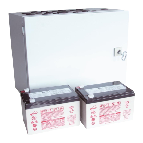
Material Metal housing for surface mounting Colour Grey (RAL 7035) Size WSC 310: 300 x 400 x 120mm (HxWxD) WSC 320: 300 x 400 x 210mm (HxWxD) Weight WSC 310: 6kg no batteries, 10.8kg with batteries (2 x WSA 007) WSC 320: 8.6kg no batteries, 16.6kg with batteries (2 x WSA 012) Protection class IP54... -
Page 12: Assembly Instructions
7.5 Assembly instructions Always have assembly, installation, repair and maintenance of smoke and heat extraction systems carried out by qualified personnel trained for this purpose. Rules to be adhered to for setting up and installation The following safety relevant rules have to be adhered to when planning the use of a smoke and heat extraction system and its set-up and installation: •... -
Page 13: Max Cable Length - ±24V Standard Actuators
8.2.2 Max cable length – ±24V standard actuators The actuator supply cable must have 3 wires: 2 wires current carrying / 1 wire for monitoring. ±24V standard actuators Do not use the PE wire / green/yellow wire! cable cross 3 wire 3 wire 5 wire 3 wire... - Page 14 ® When using actuators with MotorLink the max cable length is 50m regardless of the result of the above mentioned formula. Actuators with MotorLink ® Do not use the PE wire / green/yellow wire! cable cross 3 wire 3 wire 5 wire 3 wire 5 wire...
-
Page 15: Cable Plan For Connection To Wsc 310 / 320 Plus Version
Cable plan for connection to WSC 310 / 320 Plus version The above plan shows a WSC 310 panel, where the power supply unit is located in the left side of the panel wherefrom also mains is pulled. The power supply unit for the WSC 320 panel is located underneath the main control and motor line card and mains is pulled from the top right side. -
Page 16: Description Of Cards And Mains Connection
Description of cards and mains connection Each panel includes a power supply unit (SMPS) and a main control card. Motor line can input cards for additional motor lines and inputs (e.g. for key pads) as well as a fieldbus card can be added when necessary. The size of the power supply unit determines the size of the panel and the number and/or types of actuators, which can be connected to the panel. -
Page 17: Connections Between Cards
10.3 Connections between cards An overview of how the different cards are connected are shown below. 10.4 Main control card WCA 3SP – Plus Version Each WCA 3SP contains the following: - 2 motor lines for ±24V ® standard or Motorlink actuators - 2 input for keypads for comfort ventilation... - Page 18 ® X1 / X2 The WCA 3SP card has 2 motor lines (X1 and X2) for connection of ±24V standard or MotorLink actuators. ±24V standard actuators 1.1 24V / 0V 2.1 24V / 0V 1.2 Cable monitoring 2.2 Cable monitoring 1.3 0V / 24V 2.3 0V / 24V ®...
- Page 19 X3 / X4 For connection of comfort keypads. Input circuit (simplified) Data 3.1 Open 4.1 Open 3.2 Close 4.2 Close 3.3 GND / 0V 4.3 GND / 0V With the default values are input: ”Active” if the contact resistance is smaller than 2kΩ ”Inactive”...
- Page 20 X5 / X6 For connection of break glass unit type WSK 50x. Data Break glass unit bus 1 Break glass unit bus 2 5.1 24V 6.1 24V 5.2 Communication 6.2 Communication 5.3 0V 6.3 0V As the break glass units are monitored, the connection of the break glass units depends therefore of the number of smoke zones.
- Page 21 Example: 2 smoke zones and connected components; 2 break glass units type WSK 501 / 502 and 1 break glass unit type WSK 503 / 504, 3 smoke detectors WSA 300, 2 resistances WSA 501 and 3 comfort keypads. See chapter 9 "Cable plan for connection to WSC 3xx" for cable types and lengths. Connection of different types of smoke detectors to CompactSmoke™...
- Page 22 For connection of smoke detector type WSA 300. Data 7.1 + 7.2 - = 3,4mA For connection of a different type smoke detector, see above. When no smoke detector is connected to X7, a 10kΩ resistor is connected to the input. 24/48V free configurable input from e.g.
- Page 23 2 free configurable solid state outputs Output circuit (simplified) 9.3 Output A 9.4 Output A 9.5 Output B 9.6 Output B Data Max voltage: 30 Vp (peak) AC/DC Max current: 150 mA Typical On-resistance: 4,7 Ω Max On-resistance: 8 Ω Max switching speed: 2 ms, only for DC-voltage Example with solid state and relay (polarization is not important)
- Page 24 Example 1: Wind/rain and rain sensors WLA 330 and WLA 331– the settings of the sensors are set on the sensor. WLA 340 – the settings of the sensor are programmable on the smoke panels touch screen. Data 10.1 24V UPS 10.2 Wind speed 10.3 GND / 0V 10.4 24V...
- Page 25 Example 2: Wind direction dependent smoke and heat exhaust ventilation (intelligent weather station) Data 10.1 24V UPS 10.2 Wind speed / Direction 10.3 GND / 0V 10.4 24V 10.5 Rain 10.6 GND / 0V As the weather station is monitored by both communication and time out (wind without time), any cable errors will be registered.
- Page 26 For connection of master / slave connection via WSK-Link™. Data: 11.1 24V IN 11.2 Communication IN 11.3 0V IN On the master panel, either input X5 or X6 – the inputs also used for break glass units - are used for the connection.
- Page 27 Both slave and break glass units are connected to Slaves and break glass units are connected on both the master on input X5 like above example 1 – input X5 and X6 like above example 2. limiting the available cable length. E.g.
-
Page 28: Motor Line Card - Wca 3M8
10.5 Motor line card – WCA 3M8 The motor line card WCA 3M8, allows connection of additional 8 motor lines either ±24V standard ® or MotorLink The WCA 3M8 is connected to WCA 3SP via a CAN-cable (J3 on the WCA 3M8 and J4 on the WCA 3SP). -
Page 29: Keypad Card - Wca 3Ki
10.6 Keypad card – WCA 3KI The keypad card allows connection of 10 keypads. WCA 3KI requires the WCA 3M8 actuator card. The WCA 3KI is connected to WCA 3M8 via cable (J1 on the WCA 3KI and J6 on the WCA 3M8). -
Page 30: Cable Monitoring Of Actuators
Cable monitoring of actuators ® Actuators with MotorLink are monitored by data communication. When using ±24V standard actuators either diodes or 10kΩ resistors can be used for cable monitoring, see below. Configuration of cable monitoring with ±24V actuators 10kΩ-resistors (WSA 510) – monitors ever single core for interruption. -
Page 31: Touch Screen
Touch screen The plus version of the smoke ventilation panel comes with a touch screen. All connected components (actuators, break glass units, keypads, weather station etc.) are to be configured on the touch screen. The menu of the touch screen is in steps: Step 1: main menu Step 2: sub menu Step 3: configuration / showing / operation of the sub menu... -
Page 32: Rotation Of The Touch Screen
13.2 Rotation of the touch screen The picture on the touch screen can be rotated 180° Configuration – main menu All connected components (actuators, break glass units, keypads, weather station etc.) are to be configured. As the panel has pre-settings for PIN code for access to level 3, the code is to be entered before it is possible to begin the configuration (see chapter 14.15 “Log in”). -
Page 33: Motor Line
14.2 Motor line Actuators are to be connected on the motor lines. ® ±24V standard actuators and actuators with MotorLink can be connected to all motor lines, but a motor line can only be connected to one type of actuators – either ±24V standard or MotorLink ®... - Page 34 Motor lines configuration The ±24V actuators are to be configured in: 1. Output mode: informs the type of the actuator selected 2. Motor configuration 3. Stroke time 4. Motor group 5. Manual command - auto off-period 6. Retry during alarm 7.
-
Page 35: Colour Code - Motor Line
14.2.3 Colour code - motor line The overview fields on the touchscreen have colour codes for the motor lines: Colour Meaning The motor line are to be configured or there is a fault in the actuator Yellow triangle icon No configuration of the motor line / the motor line doesn’t exists Strikethrough grey Black text The motor line are configured, the actuator has not been closed... - Page 36 2. Press the number of the selected break glass unit on the overview on the touch screen → press until the menu point appears – “bip 1min for locating” is shown → press ”No” → select ”Yes”. The selected break glass unit will now beep if the door on the break glass unit is closed.
-
Page 37: Colour Code - Break Glass Unit
14.4.2 Colour code – break glass unit The overview fields on the touch screen have colour codes for the break glass units: Colour Meaning Sensor error Yellow triangle icon Black text The break glass unit are assigned to a smoke zone The reset-button in the break glass unit is pressed down (used when detecting break Blue speech bubble glass unit) -
Page 38: Local Input
Line Some of the functions referrers to ‘Line’ The % value for the lines is configurable for each smoke zone. This is done in ‘View all details’. Furthermore, in “View all details” – “Smoke zone” Line E and Line F can be given the highest priority, this is only used for fireman’s override panels. Line Function Used for... -
Page 39: Local Input - Configuration
14.6.2 Local input - configuration If component are installed in one or more inputs, these inputs are to be configured. Which item to be configured depends on the type of input – see description below. Local input - configuration Example of overview ’Local input’ with connected input card (WCA 3KI) Overview ’Local input’... -
Page 40: Usage Of Wind/Rain Sensors - Wla 33X
Input X3 and X4 on WCA 3SP and X1-X10 on WCA 8KI (binary) If local inputs are connected on the card/cards WCA 3SP and/or WCA 8KI, it/they shall be configured in: 1. Input type: informs the type of the input “Binary) (not to be configured) 2. -
Page 41: Local Output
Usage of wind/rain sensors WLA 33x with smoke zones (SZ): The used input e.g. S1X10.5 is configured as “Control smoke zones” with the function “Comfort safety” When an input is configured as “Smoke zones” and “Comfort safety” has been selected, there must in the configuration of all the motor groups be selected “Yes”... -
Page 42: Numbering Of Local Output
14.7.1 Numbering of local output All local outputs on the WCA 3SP card are numbered. The number of the output depends on its location on the card - see overview below. As the output (fault signal to Fire Alarm System) on the WCA 3SP card cannot be configured it is not numbered. Smoke ventilation panel with motor line and input cards 14.7.2 Local output - configuration If component are installed in one or more outputs, these outputs are to be configured. -
Page 43: Weather Station Type
14.8 Weather station type Here is to be selected which type of weather station –none, WOW or WLA - that is connected. (The menu “Weather” is only used for input from WCA 3SP input S1X10.2 for wind speed from WLA 340. Input S1X10.2 is also used in combination with weather station WOW 201/202/204 for wind direction dependent smoke ventilation - see section 10.4 in the installation instruction). -
Page 44: Sequence Control
14.9 Sequence control The sequence control functionality is used where the movement of a motor line must depend on an external event or situation/stage. To be used where window flabs are overlapping or where the windows cannot open (more than 15%) if the blinds are down a.s.o. The sequence control can be controlled depending on;... -
Page 45: Master / Slave Connection Of Smoke Zones
The CompactSmoke™ is tested with Hekatron THM 425-1. Technical data (of Hekatron): Configuration of magnetic clamp The configuration of magnetic clamp must be done for each motor line. Under the configuration of Motors line select Magnetic clamp. Configuration of magnetic clamp Each motor line which is configured to a magnetic clamp must be associated with a motor group. - Page 46 When panels are physically connected through the WSK-Link™ (the Master/Slave connection), safety signals and weather data signals are automatically distributed among the connected panels. Use the [ - ] button in the “Local Input” menu to associate Motor Groups with a Safety signal coming from the WSK-Link™. All Motor Groups are associated with this signal as a default.
-
Page 47: Network
To associate the slave panel with a smoke zone enter the smoke zone on the master panel. Configuration of master slave connection on master panel The smoke zone will immediately be sent to the slave panel. The associated smoke zone on the slave panel Components –... -
Page 48: Log In
14.13 Log in The access level to the smoke ventilation panel is set in four levels. Level Access to Who has access Public Everyone You can see the smoke ventilation panel from the outside with the door closed and locked Operation Chosen persons with a You can open the panel house and operate the touch screen for showing the... -
Page 49: Configuration Files On Usb
Login shall be configured in: The access levels can be locked and access to the level is only possible with a PIN code. Each level has a unique PIN code. 1. PIN 3: Configuration 2. Log out time-out (the period of access to the level before the system automatically lock the level) The appendix contains all the items that can be configured - see appendix for detailed explanation. -
Page 50: Service Timer
14.15.1 Service timer Configuation of interval between maintenance ”Reset service timer” set the last maintenance date as today. Reset off service timer The timer is set in “The interval between service”. Typically, on most markets, this will be 365 days. If the interval between maintenances is set to 0, the timer is disabled. -
Page 51: Fieldbus (Knx And Bacnet)
14.16 Fieldbus (KNX and BACnet) Only when an Fieldbus card with a fieldbus interface is added to the smoke panel will the menus associated with the vairious fieldbus options be shown. Fieldbus example An optional card with fieldbus interface is added to the panel and the menus (e.g. -
Page 52: Bacnet Configuration
14.16.2 BACnet configuration BACnet overview – object configuration Overview of the BACnet objects. For each BACnet object a direction must be configured None Input Output When objects are configured as inputs or outputs, the controlled motor group or smoke zone as well as its function must also be configured. -
Page 53: Configuration Missing - Main Menu
Operation types Motor lines and motor groups They can be operated absolutely (percentage of full open) or relatively on the keypad ‘open/stop/close’ showed on the touch screen. Smoke zones They can be operated in ‘Alarm’ or ‘Reset’ Example Manual operation of a motor line If ’All’... -
Page 54: View All Details - Main Menu
18.1.1 Blown battery fuse – 20A fast Additionally, an error on the ”Battery status” can also be triggered if the fuse (20A fast) is blown. The fuse is located in bottom left corner of the main card. Location of 20A fast fuse View all details –... -
Page 55: Commissioning And Test Run
Remote control can be configured in: To enable remote control of the panel it is necessary to allow remote control. This is done in the configuration of the system. Configuration of remote control IP-address of the CompactSmoke™ Identification of the IP-address Start the ’WMaFlexiSmokeRemote program’... -
Page 56: With Mains Voltage, With Accumulator
21.3 With mains voltage, with accumulator a) Remove the protection film from one face of the supplied foam rubber. Glue each foam rubber to the bottom side of the accumulators. Connect the accumulators to the black accumulator bridge according to the wiring diagram, then connect the red and the black connection cable to the red and the black flat plug. -
Page 57: Maintenance Agreements
The smoke ventilation panel will signal fault on the batteries if the battery voltage is below 17V. Within the framework of the service, they have to be replaced after the specified maximum 4 year operating period. Dispose of used batteries according to the National regulation. CAUTION: RISK OF EXPLOSION IF BATTERIES ARE REPLACED BY AN INCORRECT TYPE.
Need help?
Do you have a question about the CompactSmoke WSC 310 and is the answer not in the manual?
Questions and answers