Binder ULTRA.Guard UF V 500 Operating Manual
Uf v series ultra low temperature freezers uf v (e3) with rd4 controller
Hide thumbs
Also See for ULTRA.Guard UF V 500:
- Translation of the original operating manual (113 pages) ,
- Operating manual (123 pages) ,
- Operating manual (117 pages)
Table of Contents
Advertisement
Operating Manual
Translation of the Original Operating Manual
ULTRA.Guard™
Ultra Low Temperature Freezers UF V (E3)
with RD4 Controller
Model
Model version
UF V
UF V 500
UFV500-230V
UF V 700
UFV700-230V
BINDER GmbH
Address: Post office box 102, 78502 Tuttlingen, Germany Phone: +49 7462 2005 0
Fax: +49 7462 2005 100 Internet: http://www.binder-world.com
E-mail: info@binder-world.com Service Hotline: +49 7462 2005 555
Service Fax: +49 7462 2005 93 555 Service E-Mail: service@binder-world.com
Service Hotline USA: +1 866 885 9794 or +1 631 224 4340 x3
Service Hotline Asia Pacific: +852 390 705 04 or +852 390 705 03
Service Hotline Russia and CIS: +7 495 988 15 16
Version 09/2018
Art. No.
9020-0347, 9120-0347
9020-0348, 9120-0348
Voltage
230 V
230 V
Art. No. 7001-0374
Advertisement
Table of Contents

Related Manuals for Binder ULTRA.Guard UF V 500


Summary of Contents for Binder ULTRA.Guard UF V 500
- Page 1 Fax: +49 7462 2005 100 Internet: http://www.binder-world.com E-mail: info@binder-world.com Service Hotline: +49 7462 2005 555 Service Fax: +49 7462 2005 93 555 Service E-Mail: service@binder-world.com Service Hotline USA: +1 866 885 9794 or +1 631 224 4340 x3 ...
-
Page 2: Table Of Contents
Contents SAFETY ........................6 Legal considerations ........................... 6 Structure of the safety instructions ...................... 6 1.2.1 Signal word panel ........................7 1.2.2 Safety alert symbol ........................7 1.2.3 Pictograms ..........................8 1.2.4 Word message panel structure ....................8 Localization / position of safety labels at the chamber ................ 9 Type plate ............................ - Page 3 PLACING SAMPLES IN STORAGE IN THE FREEZER ........41 SETTING SPECIAL CONTROLLER FUNCTIONS ..........42 10. PASSWORD ......................43 10.1 Password request ..........................43 10.2 Assign and modify a password ......................43 10.2.1 Assign and modify the User password ..................44 10.2.2 Assign and modify the Admin password ..................
- Page 4 15.2.3 Assigning the IP address ......................66 15.2.4 Setting the subnet mask ......................67 15.2.5 Setting the standard gateway ....................68 15.2.6 Assigning the DNS server address ..................68 16. ACCESS CODES (OPTION “DOOR ACCESS SYSTEM”) ......... 69 16.1 Assigning the access codes ......................69 16.2 Opening the chamber door with the access code ................
- Page 5 24.4.2 Cleaning the condenser ......................93 24.4.3 De-icing and defrosting ......................93 24.5 Sending the chamber back to BINDER GmbH ................. 94 25. DISPOSAL ......................94 25.1 Disposal of the transport packing ...................... 94 25.2 Decommissioning ..........................95 25.3 Disposal of the chamber in the Federal Republic of Germany ............95 25.4 Disposal of the chamber in the member states of the EU except for the Federal Republic of...
-
Page 6: Safety
Understanding and observing the instructions in this operating manual are prerequisites for hazard-free use and safety during operation and maintenance. In no event shall BINDER be held liable for any dam- ages, direct or incidental arising out of or related to the use of this manual. -
Page 7: Signal Word Panel
1.2.1 Signal word panel Depending on the probability of serious consequences, potential dangers are identified with a signal word, the corresponding safety color, and if appropriate, the safety alert symbol. DANGER Indicates an imminently hazardous situation that, if not avoided, will result in death or serious (irreversible) injury. -
Page 8: Pictograms
1.2.3 Pictograms Warning signs Very cold surface Stability hazard Electrical hazard Explosive atmosphere suffocation hazard Gas cylinders Pollution Hazard Harmful substances Risk of corrosion and / Biohazard or chemical burns Mandatory action signs Lift with mechanical Mandatory regulation Read operating Disconnect the power assistance instructions... -
Page 9: Localization / Position Of Safety Labels At The Chamber
Figure 1: Position of labels on the ultra-low temperature freezer UF V Keep safety labels complete and legible. Replace safety labels that are no longer legible. Contact BINDER Service for these replacements. UF V (E3) 09/2018 Page 9/116... -
Page 10: Type Plate
78532 Tuttlingen / Germany www.binder-world.com Figure 2: Type plate (example UF V 500 (E3) standard chamber) Indications of the type plate (example) Information BINDER Manufacturer: BINDER GmbH UF V 500 Model designation ULTRA.GUARD ULT Freezer Device name: “ULTRA.GUARD” ultra-low temperature freezer Serial No. -
Page 11: General Safety Instructions On Installing And Operating The Chamber
213-850 on safe working in laboratories (formerly BGI/GUV-I 850-0, BGR/GUV-R 120 or ZH 1/119, issued by the employers’ liability insurance association) (for Germany). BINDER GmbH is only responsible for the safety features of the chamber provided skilled electricians or qualified personnel authorized by BINDER perform all maintenance and repair, and if components relating to chamber safety are replaced in the event of failure with original spare parts. - Page 12 WARNING Contamination with toxic, infectious or radioactive substances. Danger of intoxication. Danger of infection. Protect the interior of the chamber against contamination by toxic, infectious or radioac- tive substances. Take appropriate measures when bringing in or taking out toxic, infectious or radioac- tive substances.
-
Page 13: Intended Use
Such ingredients include in particular acids and halides. Any corrosive damage caused by such ingredients is excluded from liability by BINDER GmbH. In case of foreseeable use of the chamber there is no risk for the user through the integration of the chamber into systems or by special environmental or operating conditions in the sense of EN 61010- 1:2010. -
Page 14: Measures To Prevent Accidents
Measures to prevent accidents The operator of the chamber must observe the following regulation: Occupational Safety Regulations. Operation of refrigeration chambers, heat pumps and cooling systems (GUV-R 500 chap. 2.35) (for Ger- many). Following measures have been taken by the manufacturer in order to prevent ignition and explosions: •... -
Page 15: Chamber Description
Chamber description The ULTRA.Guard™ ultra-low temperature freezers UF V were produced with great care using the latest tools for development and production. They were optimized for safe long-term storage of samples in the ultra-low temperature range. You can operate the freezer in a temperature range from -86 °C / -122.8 °F up to -40 °C / -40 °F. - Page 16 The freezer is regularly equipped with an Ethernet interface (chap. 22.1) for computer communication, enabling monitoring via a network. The BINDER communication software APT-COM™ 3 / 4 DataControl- System (option, chap. 22.2) permits networking of up to 40 chambers and connection to a computer, as well as recording and representing temperature data.
-
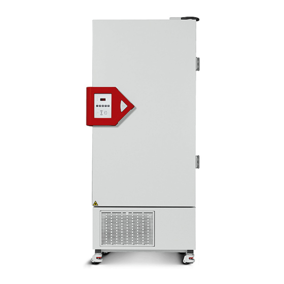
Page 17: Chamber Overview
Chamber overview Optional equipment: Standard equipment “Door access system” Figure 3: Ultra-low temperature freezer UF V (example UF V 700), front view Outer door Door lock and controller housing (description chap. 2.2) Door handle Compressor housing Air filter flap (checking and cleaning / replacing the filter chap. 24.4.1) Castors (front castors lockable by breaks) UF V (E3) 09/2018 Page 17/116... - Page 18 Figure 4: Ultra-low temperature freezer UF V 700, open Outer door Door lock and controller housing (description chap. 2.2) Door handle Compressor housing Air filter flap (checking and cleaning / replacing the filter chap. 24.4.1) Castors (front castors lockable by breaks) Compartment with variable shelf Compartment door UF V (E3) 09/2018...
-
Page 19: Door Lock And Controller Housing
Door lock and controller housing The controller operator panel is integrated in the freezer‘s door lock and controller housing (B). With the standard chamber a door handle (C) serves to open and close the chamber door. Front view Left chamber side Figure 5: Standard chamber: Door lock and controller housing with controller operator panel and door handle Chambers with the “Door access system “option are equipped with an electromechanical door locking and... -
Page 20: Operating The Numpad (Option "Door Access System")
2.2.1 Operating the NumPad (option “Door access system”) Combined with the electromechanical door locking the NumPad permits personalized access control to the freezer. Figure 7: Door lock and controller housing with “Door access system” option: Numpad, controller operating panel and pushbutton “OPEN” to open the chamber door Controller RD4 operating panel Pushbutton “OPEN”... -
Page 21: Main Power Switch
Main power switch The main power switch is located on the bottom right side of the chamber. In addition, a lockable protective flap covering the main power switch is optionally available. It can be un- locked with a key and then removed. (5a) Standard chamber Chamber with optional lockable protective flap... -
Page 22: Chamber Rear
Chamber rear (6a) (6b) (6b) emergency cooling Chamber with CO emergency cooling Chamber without CO (option) Figure 11: Chamber rear (6a) 28 mm access port to connect the der CO emergency cooling (option) or for cable of a supplemen- tary measuring device (6b) 28 mm access port, e.g., for cable of a supplementary measuring device Connecting socket for IEC connector plug with strain relief... -
Page 23: Doors
(10) (11) Figure 12: Connection panel (I) on the chamber rear Ethernet interface (Chap. 22.1) Connection socket for zero-voltage relay alarm contact (chap. 14.4.7) (10) Connection socket for analog output 4-20 mA (option, chap. 22.3) (11) Connection socket for the electrical connection of the CO emergency cooling (option, chap. -
Page 24: Drain Well For Condensate During Defrosting (Option)
Drain well for condensate during defrosting (option) The drain well collects the dripping water when defrosting. Strong magnets on the drain well sides fix it on the chamber. Attach the drain well to the freezer. Its first level rests on the lower housing panel. The gasket is aligned to the bottom edge of the freezer interior. -
Page 25: Completeness Of Delivery, Transportation, Storage, And Installation
Completeness of delivery, transportation, storage, and installation Unpacking, and checking equipment and completeness of delivery After unpacking, please check the chamber and its optional accessories, if any, based on the delivery receipt for completeness and for transportation damage. Inform the carrier immediately if transportation damage has occurred. -
Page 26: Guidelines For Safe Lifting And Transportation
Note on second-hand chambers (Ex-Demo-Units) Second-hand chambers are chambers that have been used for a short time for tests or exhibitions. They are thoroughly tested before resale. BINDER ensures that the chamber is technically sound and will work flawlessly. Second-hand chambers are marked with a sticker on the chamber door. Please remove the sticker before commissioning the chamber. -
Page 27: Transport Outside A Building
To move the freezer through narrow passages (doors, narrow corridors), open the chamber door: 900 mm 830 mm Figure 14: UF V with open chamber door For transport outside a building use technical equipment (chap. 3.2.2). 3.2.2 Transport outside a building Before moving the chamber unlock the front castors. -
Page 28: Storage
• Permissible ambient temperature range for transport: -10 °C / 14°F to +60 °C / 140°F. You can order transport packing and rolling pallets for transportation purposes from BINDER Service. Freezer transport in upright position is mandatory in order to avoid oil running out of the engine casing and resulting damages to the cooling system. - Page 29 Avoid direct solar radiation on the chamber. Do not place the freezer in direct vicinity of cham- bers with a high heat emission. • Permissible ambient humidity: 70% r.h. max., non-condensing. • Installation height: max. 2000 m / 6561.7 ft above sea level. Minimum distances: •...
-
Page 30: Installation And Connections
Installation and connections Operating instructions Depending on the application and location of the chamber, the operator of the freezer must provide the relevant information for safe operation of the chamber in a set of operating instructions. Keep these operating instructions with the chamber at all times in a place where they are clearly visible. -
Page 31: Adjustable Shelves
Adjustable shelves The scope of delivery comprises three adjustable shelves. You can mount them and further optional shelves in different positions of the lateral walls in 24 mm / 1 inch steps. In standard position, the shelves are placed with a distance of 310mm / 12.2 in, forming the bottom of the compartments, thus making available the maximum space for optional inventory systems. - Page 32 For optimal use of space, we recommend the following shelf positions: Position of 3 shelves to obtain 4 Position of 4 shelves (1 x optional) Position of 3 shelves to obtain the compartments with equal ceiling to obtain 5 compartments with maximum sample storage space: 2 height equal ceiling height...
-
Page 33: Connections Of Cooling Water For Chambers With Water Cooling (Option)
Connections of cooling water for chambers with water cooling (option) The water cooling reduces the heat, which is emitted during cooling operation to the ambient air. An enclosure inside the chamber contains the connection kit for the cooling water inlet and outlet. „OUT“... -
Page 34: Connection Of Cooling Water Inlet For Water Cooling
Any problems and malfunctions that might arise following use of water of deviating quality is excluded from liability by BINDER GmbH. This includes in particular a high particle content, which may result in blockage of the water flow control valve. - Page 35 Protection principle of the hose burst protection The hose burst protection device serves to protect the environment against flooding caused by burst water hoses. It is intended for the operation of the device at a tap water line. If the freezer is operated in a cycle of cooling water or air conditioning water, the user should check whether the hose burst protection device provides sufficient protection.
-
Page 36: Electrical Connection
The protective conductors of the socket and plug must be compatible! • Only use original connection cables from BINDER. • Prior to connection and start-up, check the power supply voltage. Compare the values to the specified data located on the chamber’s type plate (located on the left-hand side of the chamber, bottom right-... -
Page 37: Functional Overview Of The Rd4 Chamber Controller
“Set points” menu directly at the controller or use the APT-COM™ 3 DataControlSystem software (option) specially developed by BINDER. The controller offers various notifications and alarm messages with visual and audible indication. All con- troller setting remain valid until the next manual change. They are stored also after turning off the cham- ber. -
Page 38: Menu Structure Of The Controller And Access Levels
• Admin: The password enables access to advanced controller functions and settings. Factory setting is 00 01. • Service: The password enables access to all controller functions (for BINDER Service only). As soon as a password has been assigned, access to the respective functions is blocked and only availa- ble after entering the correct password. -
Page 39: Start Up
Unless noted otherwise, the figure in this manual show the functional range, which is available for the user with “Admin” authorization level Note: When specifying the path to the respective function, the possibly required entry of a password is not listed. -
Page 40: Temperature Set-Point Entry
• Temperature unit (chap. 12.2): Use the arrow buttons to select the desired temperature unit, confirm with the OK button. • Current date (chap. 12.3), format DD MM YYYY: Use the arrow buttons to set the day, continue with the OK button. Use the arrow buttons to set the month, continue with the OK button. -
Page 41: Placing Samples In Storage In The Freezer
Placing samples in storage in the freezer Before storing valuable samples, conduct a 10-days test run at the desired temperature. This helps to detect transport damages like capillary cracks. Then you can load the freezer with the precooled samples. WARNING: If customer should use a freezer running in non-supervised continuous operation, we strongly recommend in case of inclusion of irrecoverable specimen or samples to split such specimen or samples and store them in at least two chambers, if this is feasible. -
Page 42: Setting Special Controller Functions
Setting special controller functions In the “Functions on/off” menu you can define the switching state of up to 4 controller functions. Required access level: “User”. Path: Normal display Setpoints Functions on/off With optional CO emergency cooling: Path: Normal display Setpoints Functions on/off The functions are displayed from left to right. -
Page 43: Password
Password 10.1 Password request To access menus for which access is restricted, you must enter the corresponding password. After calling the appropriate menu function with the OK button the password request appears. Password request. The left two digits are flashing. Enter the desired numbers with the arrow buttons. -
Page 44: Assign And Modify The User Password
10.2.1 Assign and modify the User password Path: Normal display Settings Chamber Password User Press the OK button to enable the setting. Setting the User password. The left two digits are flashing. Enter the desired numbers with the arrow buttons. Confirm the setting with the OK button. -
Page 45: Performance During And After Power Failure And Shut Down
10.3 Performance during and after power failure and shut down Standard chamber: During a power supply failure, all controller functions are shut down. Chamber with option “battery-buffered alarm system”: During a power supply failure the battery maintains the controller functions. The controller display is dark and can be activated for 5 seconds by pressing any button. -
Page 46: Setting The Safety Controller Mode
Example: Desired temperature value: -86 °C, desired safety controller value: -60 °C. Possible settings for this example: Temperature set point Safety controller mode Safety controller value Limit Limit value -60 °C -86 °C Offset Offset value 26 °C 11.1 Setting the safety controller mode Required access level: “User”. -
Page 47: Message And Measures In The State Of Alarm
Setting the safety controller value with “Offset” safety controller mode The current value flashes. Enter the desired offset value with the arrow buttons. Confirm the entry with the OK button. Offset With the Back button you can go back to the “Safety controller”... -
Page 48: General Controller Settings
General controller settings The general settings can be accessed in the “Settings” submenu, which is available for users with “Ser- vice” or “Admin” authorization level. It serves to enter date and time, select the language for the controller menus and the desired temperature unit and to configure the controller’s communication functions. The display of some network settings is available for all users in the “Chamber info”... -
Page 49: Setting The Current Date
12.3 Setting the current date Required access level: “Admin”. Following start-up of the chamber (chap. 6), it is “User”. Path: Normal display Settings Chamber Date Press the OK button to enable the setting. Setting the date: day The current setting flashes. Enter the current day with the arrow but- tons. -
Page 50: Setting The Current Time
12.4 Setting the current time Required access level: “Admin”. Following start-up of the chamber (chap. 6), it is “User”. Path: Normal display Settings Chamber Time Press the OK button to enable the setting. Setting the time: hours The current setting flashes. Enter the current hour with the arrow but- tons. -
Page 51: Setting The Chamber Address
12.6 Setting the chamber address This setting is required for the communication with the BINDER communication software APT-COM 3 DataControlSystem. The chamber address settings in the chamber controller and in the software must be identical. Required access level: “Admin”. Path:... -
Page 52: Tolerance Range And Alarm Delay Settings
Tolerance range and alarm delay settings In this menu you can define the deviation between the actual value and setpoint of, which that shall cause a tolerance range alarm. The entered value defines the limit of permitted deviations from the set-point (exceeding and falling below). -
Page 53: Setting The Temperature Tolerance Range
With the arrow-up button you can go back to the door alarm delay setting. With the arrow-down button you can now change to the temperature tolerance range setting. With the Back button you can go back to the “Various” submenu and, repeatedly pressing it, to Normal display. -
Page 54: Alarm Functions
• 12 hours after start-up, if the set- Continuous compressor operation, point wasn’t reached refrigeration system defective. Con- “Continuous operation” • 60 minutes after reaching the set- tact BINDER Service. point Clean / replace the condenser air “Condenser temp.” immediately filter (chap. 24.4.1) Compressor defective. - Page 55 Moment of Alarm message and Condition Alarm message switching the zero-voltage relay alarm output Safety controller temperature sen- “Safety control sensor” immediately sor defective Temperature display shows “- - - - “ or Inner temperature sensor and safe- “<-<-< “ or “>->->” ty controller temperature sensor immediately defective.
-
Page 56: Information Messages
14.2 Information messages Information messages provide information about settings made and the condition of the optional battery. In Normal display a text message indicates the condition. The “Information” icon is lit. Information message (example: CO emergency cooling test run is active) CO2 cooling test acti Information messages overview:... -
Page 57: Required Actions In Case Of An Alarm
• Input of large quantities of samples which were precooled with liquid nitrogen. Reset the alarm with the OK button. • Possible cause: Continuous operation of the refrigeration machine after failure of one or several tem- perature sensors (chap. 14.4.6). In addition there is continuous operation alarm. Contact BINDER Ser- vice. UF V (E3) 09/2018... -
Page 58: Door Open Alarm
• If these points do not reveal the source of the fault, it may be that the chamber is faulty. Please contact BINDER Service. If the same alarm recurs, please contact BINDER Service. 14.4.3 Door open alarm The open and closed condition of the chamber door is controlled via the door contact switch. The temper- ature rise when the door is opened causes the refrigerating machine to turn on. -
Page 59: Messages On The Battery Management System (Chamber With Option "Battery-Buffered Alarm System")
Actions: • Check the power supply. • Check the charging voltage in the controller menu (chap. 19.2) • With defective battery: replace battery. Contact BINDER Service. • Reset alarm message. It will not reset automatically. UF V (E3) 09/2018 Page 59/116... -
Page 60: Messages Referring To Temperature Sensor Failure
• Refrigeration is turned on permanently. Actions: • Please contact BINDER Service. • If the temperature rises, i.e. the refrigerating machine is defective (safety controller temperature alarm and / or tolerance range alarm): • Transfer the material to another freezer. -
Page 61: Messages Referring To Co Emergency Cooling (Option Co Emergency Cooling)
• Battery voltage is very low (< 12 V). Actions: • Check the battery connections • Charge the battery (charging mode: current, approx. 160 mA) • If it is defective, replace the battery. Contact BINDER Service • Reset the alarm message. UF V (E3) 09/2018 Page 61/116... -
Page 62: Zero-Voltage Relay Alarm Output
14.5 Zero-voltage relay alarm output Collective alarm output via the zero-voltage relay alarm contact The freezer is equipped at the rear with a zero-voltage relay output (9), which permits the transmission of alarms to an external monitoring system in order to monitor and record the alarm signals. The zero-voltage relay alarm output switches immediately, as soon as the red LED lights up on the controller display. -
Page 63: Ethernet Network Settings
Ethernet network settings The settings of this submenu are used for networking chambers with an Ethernet interface, e.g. to connect them with BINDER’s communication software APT-COM™ 3 DataControlSystem (option, chap. 22.2). 15.1 Showing the network settings Required access level: “User”. -
Page 64: Showing The Ip Address
15.1.2 Showing the IP address Path: Normal display Chamber info Ethernet IP ad- dress Display of the IP address (example) Toggle forth and back with the Back button and the OK button. IP address 0.0.0.0 With the arrow-down button you can now change to the next parameter (subnet mask). With the Back button you can go back to the “Ethernet”... -
Page 65: Showing The Dns Server Address
15.1.5 Showing the DNS server address Path: Normal display Chamber info Ethernet DNS server address Display of the DNS server address (example) Toggle forth and back with the Back button and the OK button. DNS server address 0.0.0.0 With the arrow-down button you can now change to the next parameter (DNS chamber name). With the Back button you can go back to the “Ethernet”... -
Page 66: Selecting The Type Of Ip Address Assignment (Automatic / Manual)
15.2.1 Selecting the type of IP address assignment (automatic / manual) Path: Normal display Settings Ethernet IP address assignment Press the OK button to enable the setting Selection of the type of assignment of the IP address. The current setting flashes. Use the arrow buttons to select between AUTO (automatic) and MANU (manual). -
Page 67: Setting The Subnet Mask
IP address assignment (sample values). The first section of the IP address is shown. Enter the desired value with the arrow buttons. Use the OK button to confirm the entry and proceed to the second section of the IP address. IP address IP address assignment (sample values). -
Page 68: Setting The Standard Gateway
15.2.5 Setting the standard gateway Access to this function is possible only if manual IP address assignment has been selected (chap. 15.2.1) Path: Normal display Settings Ethernet Standard gateway Press the OK button to enable the setting. The standard gateway entry is done in four steps, corresponding to the number sections: (1).(2).(3).(4) Principle of entry: •... -
Page 69: Access Codes (Option "Door Access System")
Access codes (option “Door access system”) Chambers with the “Door access system” option are equipped with an electronic access control via NumPad, which, in connection with the electromechanical door locking, enables personalized access con- trol. 16.1 Assigning the access codes You can assign up to 20 access codes as four-digit number combinations. -
Page 70: Opening The Chamber Door With The Access Code
16.2 Opening the chamber door with the access code Once at least one access code has been assigned, it is required to open the chamber door. Enter the four digits of the access code directly on the NumPad. Enter the digits quickly one after the oth- er. -
Page 71: Data Recorder
(chap. 17.3). Temperature values are always given out in °C. • Chamber data for BINDER Service “DL2” This data is intended for use by BINDER Service. The storage rate is fix (1 minute). Temperature val- ues are always given out in °C. -
Page 72: Setting The Storage Rate For The "Dl1" Recorder Data
17.4 Deleting the data recorder When importing a configuration via USB stick and when loading a new firmware version by BINDER ser- vice, the entire data memory is deleted. BINDER service can also install the configuration by means of a setup program without deleting the data. -
Page 73: Usb-Menu: Data Transfer Via Usb Interface
For detailed information on the file content see chap. 17.1. • Service data The "Service" folder is created on the USB stick and can be sent to BINDER Service. In addition to the configuration and recorder data, it contains further service-relevant information. -
Page 74: Export Functions
18.3 Export functions Required access level: any user Function “Export configuration”. To write the configuration data from the controller to the USB stick, press the OK button. Export configuration With the arrow-down button you can now change to the next function. Function “Export recorder data”. -
Page 75: Error During Data Transmission
18.5 Error during data transmission In the event of an error, the message ERR (error) is displayed. Read error (example). Import configuration. 18.6 Removing the USB stick Logging off the USB stick is not possible / required. Be sure that no data recording is running (chap. 18.4). After removing the USB stick, the controller is back in the same menu as before when connecting the USB stick. -
Page 76: Charging Voltage
19.2 Charging voltage This menu shows the battery’s current charging voltage. The correct voltage is > 12 V. As soon as the charging voltage falls below the limit value of 12 V, the information message “Low battery voltage” is emitted. This happens on battery power and on line power (chap. 14.4.5). Required access level: “User”. -
Page 77: Activating The Service Setpoint
20.2 Activating the service setpoint Required access level: “User”. Path: Normal display Setpoints Functions on/off Service setpoint on/off Path with optional CO emergency cooling: Normal display Setpoints Functions on/off Service setpoint on/off Press the OK button to enable the setting. Setting function 3 “Service setpoint on/off”. -
Page 78: Co Emergency Cooling (Option)
emergency cooling (option) (16) (12) (14) (17) (15) (11) Figure 23: Rear view UF V with CO emergency cooling system emergency cooling (13) Connection socket for the electrical connection of the CO emergency cooling (14) discharge outlet to connect a discharge hose (15) Cable to connection socket (11) for the electrical connection of the CO emergency cooling... -
Page 79: Connecting And Exchanging The Pressurized Co Cylinder
The supplied gas hose (17) is already connected with the CO emergency cooling system. The user shall not remove this connection. When replacing the gas hose is required, please contact BINDER Service. To connect the pressurized CO cylinder, connect the free end of the gas hose to the gas cylinder (wrench size A/F 30 mm / 1.2 in). - Page 80 The valve of the gas cylinder always must be closed before screwing on or unscrewing the gas hose WARNING Opening the cylinder valve when the cylinder is not connected. Sudden release of the stored pressure energy. Risk of injury. Close the gas cylinder valve before connecting or removing the gas hose. Secure the pressurized gas cylinder against falling and other mechanical damage.
-
Page 81: Operating The Co Emergency Cooling System
• Make sure that operating instructions on the connection and exchange of the pressurized gas cylinders are attached in the vicinity of the pressurized gas cylinders. The instructions shall contain all required safety-related information in an intelligible form. • Laboratories in which compressed gas cylinders are installed must be labeled with the warning sign W019 “Warning of gas cylinders”. - Page 82 WARNING High concentration of CO (> 4 vol.-%). Risk of death by suffocation. Danger of poisoning. Operate the CO emergency cooling only in a well-ventilated room. Ensure technical ventilation measures. Install a suitable conduct at the CO discharge outlet of the emergency cooling system.
-
Page 83: Settings On The Chamber Controller
21.3 Settings on the chamber controller The following controller menus are available only with chambers equipped with the optional CO emer- gency cooling. 21.3.1 Setting the CO emergency cooling temperature setpoint Required access level: “User”. Path: Normal display Setpoints CO2 emergency cooling Press the OK button to enable the setting. -
Page 84: Test Run Of The Co 2 Emergency Cooling
Normal display with running emergency cooling, showing the alarm message “CO2 emergency cooling” CO2 emergency cool- The valve of the CO gas cylinder must be open, otherwise pressure alarm will occur. Inactivating the CO emergency cooling 1. Inactivate the CO emergency cooling at the controller. -
Page 85: Data Monitoring And Recording
Data monitoring and recording 22.1 Ethernet interface The chamber is regularly equipped with an Ethernet interface (8) that can connect the BINDER communi- cation software APT-COM™ 3 DataControlSystem (option). The MAC Address is indicated in the “Ether- net” controller menu (chap. 15.1.1). -
Page 86: Chamber Inventory: Storage Rack Systems And Cryo Boxes (Option)
Chamber inventory: Storage rack systems and cryo boxes (option) 23.1 Storage rack systems with or without cryo boxes For optimum use of the available space of the freezer compartments, the following racks are available: • Side access racks, aluminum or stainless steel •... -
Page 87: Maintenance, Cleaning, And Service
With an increased amount of dust in the ambient air, clean the condenser fan (by suction or blowing) sev- eral times a year. Check the condenser air filter frequently and clean / replace it if necessary (chap. 24.4.1). We recommend taking out a maintenance agreement. Please consult BINDER Service. BINDER telephone hotline: +49 (0) 7462 2005 555... -
Page 88: Service Reminder
24.2 Service Reminder After the recommended maintenance interval, a message appears on the controller. After one year of operation, the message “Maintenance due” appears in the text field of the controller display. Maintenance due! Press the OK button, to confirm the message. After one week of operation, the message reappears. If you press down the OK button for 10 seconds, the message is reset for one year. - Page 89 Do NOT use a neutral cleaning agent on zinc coated surfaces. Do not use cleaning agents that may cause a hazard due to reaction with components of the device or the charging material. If there is doubt regarding the suitability of cleaning products, please contact BINDER service.
-
Page 90: Decontamination
For chemical disinfection, we recommend using the disinfectant spray Art. No. 1002-0022. Any corrosive damage that may arise following use of other disinfectants is excluded from liability by BINDER GmbH. With every decontamination method, always use adequate personal safety controls. - Page 91 Recommended precautions: To protect the eyes use sealed protective goggles. CAUTION Eye contact. Eye damage due to chemical burns. ∅ Do NOT empty into drains. Wear protective goggles. After using the disinfectant spray, allow the chamber to dry thoroughly, and aerate it sufficient- Alternatively you can use the following disinfectants (apply on a cloth): Standard commercial surface disinfectants free from acid or halides (not dripping).
-
Page 92: Maintenance Work By The Customer
24.4 Maintenance work by the customer 24.4.1 Checking and cleaning / replacing the condenser air filter The condenser air filter prevents accumulation of dust on the condenser. If the filter is blocked by dust this may cause decrease or failure of refrigeration. Check the air filter visually for soiling every month. -
Page 93: Cleaning The Condenser
24.4.2 Cleaning the condenser Every 6 months remove by suction any visible dust on the condenser lamellas with a vacuum cleaner. If appropriate, blow through the lamellas with compressed air. With an increased amount of dust in the ambient air, clean the condenser several times a year. In this case we recommend to weekly check the condenser lamellas (behind the air filter flap (E). -
Page 94: Sending The Chamber Back To Binder Gmbh
24.5 Sending the chamber back to BINDER GmbH If you return a BINDER product to us for repair or any other reason, we will only accept the product upon presentation of an authorization number (RMA number) that has previously been issued to you. An au- thorization number will be issued after receiving your complaint either in writing or by telephone prior to your sending the BINDER product back to us. -
Page 95: Decommissioning
(Elektro- und Elektronikgerätegesetz, ElektroG from 20 Octo- ber 2015, BGBl. I p. 1739) or contact BINDER service who will organize taking back and disposal of the chamber according to the German national law for electrical and electronic equipment (Elektro- und El- ektronikgerätegesetz, ElektroG from 20 October 2015, BGBl. -
Page 96: Disposal Of The Chamber In The Member States Of The Eu Except For The Federal Republic Of Germany
According to Annex I of Directive 2012/19/EU of the European Parliament and of the Council on waste electrical and electronic equipment (WEEE), BINDER devices are classified as “monitoring and control instruments” (category 9) only intended for professional use“. They must not be disposed of at public col- lecting points. -
Page 97: Disposal Of The Chamber In Non-Member States Of The Eu
25.5 Disposal of the chamber in non-member states of the EU CAUTION Alteration of the environment. For final decommissioning and disposal of the chamber, please contact BINDER Ser- vice. Follow the statutory regulations for appropriate, environmentally friendly disposal. -
Page 98: Troubleshooting
Wrong voltage. voltage (chap.4.5). Check chamber fuse and replace it Chamber without function. Chamber fuse has responded. if appropriate. If it responds again, contact BINDER service. Controller defective. Contact BINDER service. Alarm message “Door open” Chamber door open. Close chamber door. - Page 99 Cause of alarm persists. alarm state continues, contact not cancel the alarm state. BINDER service. Only qualified service personnel authorized by BINDER must perform repair. Repaired chambers must comply with the BINDER quality standards. UF V (E3) 09/2018 Page 99/116...
-
Page 100: Technical Description
December 1996 by TÜV CERT). All test equipment used is subject to the administration of measurement and test equipment that is also a constituent part of the BINDER QM DIN EN ISO 9001 systems. They are controlled and calibrated to a DKD-Standard at regular intervals. -
Page 101: Technical Data
27.4 Technical data Chamber size Exterior dimensions Width, gross (including hinges, door lock and controller mm / inch 920 / 36.2 1204 / 47.4 housing) Height, gross (incl. castors) mm / inch 1966 / 77.4 1966 / 77.4 Depth, gross (including power connection, without door lock and controller housing (equals depth when door mm / inch 850 / 33.5... - Page 102 +22 °C +/- 3°C / 71.6 °F +/- 5.4 °F and a power supply voltage fluctuation of +/-10. Technical data is determined in accordance to BINDER Factory Standard Part 2:2015 and DIN 12880:2007. All indications are average values, typical for chambers produced in series. We reserve the right to change technical specifications at any time.
-
Page 103: Equipment And Options (Extract)
27.5 Equipment and options (extract) To operate the chamber, use only original BINDER accessories or accessories / components from third-party suppliers authorized by BINDER. The user is responsible for any risk arising from using unauthorized accessories. Regular equipment RD4 microprocessor controller for temperature... -
Page 104: Optional Equipment, Accessories And Spare Parts (Extract)
27.6 Optional equipment, accessories and spare parts (extract) BINDER GmbH is responsible for the safety features of the chamber only provided skilled elec- tricians or qualified personnel authorized by BINDER perform all maintenance and repair, and if components relating to chamber safety are replaced in the event of failure with original spare parts. - Page 105 DL440500 Calibration service Art. no. Calibration of temperature including certificate (1 measuring point) DL300201 Spatial temperature measurement including certificate (20 measuring points) DL300620 For information on components not listed here, please contact BINDER Service. UF V (E3) 09/2018 Page 105/116...
-
Page 106: Dimensions Uf V 500 (E3)
27.7 Dimensions UF V 500 (E3) Dimensions in mm UF V (E3) 09/2018 Page 106/116... -
Page 107: Dimensions Uf V 700 (E3)
27.8 Dimensions UF V 700 (E3) Dimensions in mm UF V (E3) 09/2018 Page 107/116... -
Page 108: Certificates And Declarations Of Conformity
Certificates and declarations of conformity 28.1 EU Declaration of Conformity UF V (E3) 09/2018 Page 108/116... - Page 109 UF V (E3) 09/2018 Page 109/116...
-
Page 110: Product Registration
Product registration UF V (E3) 09/2018 Page 110/116... -
Page 111: Contamination Clearance Certificate
Contamination clearance certificate 30.1 For chambers located outside the USA and Canada Declaration regarding safety and health Erklärung zur Sicherheit and gesundheitlichen Unbedenklichkeit The German Ordinance on Hazardous Substances (GefStofV), and the regulations regarding safety at the workplace, require that this form be filled out for all products that are returned to us, so that the safety and the health of our employees can be guaranteed. - Page 112 Kind of transport / transporter / Transportweg/Spediteur: Transport by (means and name of transport company, etc.) Versendung durch (Name Spediteur o.ä.) ___________________________________________________________________________________ Date of dispatch to BINDER GmbH / Tag der Absendung an BINDER GmbH ___________________________________________________________________________________ UF V (E3) 09/2018 Page 112/116...
- Page 113 We are aware that, in accordance with Article 823 of the German Civil Code (BGB), we are directly liable with regard to third parties, in this instance especially the employees of BINDER GmbH, who have been entrusted with the handling / repair of the unit / component. / Es ist uns bekannt, dass wir gegenüber Dritten –...
-
Page 114: For Chambers In The Usa And Canada
Please complete this form and the Customer Decontamination Declaration (next 2 pages) and attach the required pictures. E-mail to: IDL_SalesOrderProcessing_USA@binder-world.com After we have received and reviewed the complete information we will decide on the issue of a RMA num- ber. Please be aware that size specifications, voltage specifications as well as performance specifications are available on the internet at www.binder-world.us... - Page 115 Customer (End User) Decontamination Declaration Health and Hazard Safety declaration To protect the health of our employees and the safety at the workplace, we require that this form is com- pleted by the user for all products and parts that are returned to us. (Distributors or Service Organizations cannot sign this form) NO RMA number will be issued without a completed form.
- Page 116 4.5 Shipping laws and regulations have not been violated. I hereby commit and guarantee that we will indemnify BINDER Inc. for all damages that are a con- sequence of incomplete or incorrect information provided by us, and that we will indemnify and hold harmless BINDER Inc.
Need help?
Do you have a question about the ULTRA.Guard UF V 500 and is the answer not in the manual?
Questions and answers