Table of Contents
Advertisement
817 Maxwell Avenue • Evansville, IN 47711 • 1-800-GO-SWING • www.escaladesports.com • ©2015 Escalade Sports
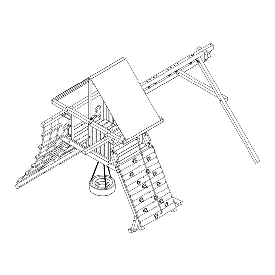
Lion's Den (PG134)
Assembly Instructions
REQUIRED TOOLS:
(2) 3/4" Sockets and Ratchets
3/4" Wrench
11/16" Wrench
1/2" Socket and Wrench
9/16" Socket and Wrench
5/16" Allen Wrench
Drill with Phillips Driver Bit
3/8" Drill Bit
1/8" Drill Bit
Hammer
Tape Measure
Utility Knife
2 ft level
Carpenters Square
6' to 8' Step Ladder
RECOMMENDED TOOLS:
Impact Driver
(2) Saw Horses
(4) Bar Clamps or C-Clamps
PG-MA-0034-01
Advertisement
Table of Contents

Related Manuals for ChildLife PG134


Summary of Contents for ChildLife PG134
- Page 1 Lion’s Den (PG134) Assembly Instructions REQUIRED TOOLS: (2) 3/4" Sockets and Ratchets 3/4" Wrench 11/16” Wrench 1/2" Socket and Wrench 9/16" Socket and Wrench 5/16" Allen Wrench Drill with Phillips Driver Bit 3/8" Drill Bit 1/8" Drill Bit Hammer Tape Measure...
- Page 2 I N T R O D U C T I O N Welcome to our family of ready-to-build backyard play equipment. CHILDLIFE playsets are designed with ease of assembly in mind and we provide these step-by-step installation instructions. After reading the information below, locate your structure site and carefully unpack parts. As you unpack your playset, keep the parts identification sheet handy and become familiar with each part before beginning assembly.
- Page 3 S A F E T Y I N S T R U C T I O N S Teach Children: • Not to walk close to, in front of, behind, or between • Not to stand in the swing seats. moving items.
-
Page 4: Pg-Ac
PARTS LIST ITEM PART NUMBER DESCRIPTION QTY. PG-44-0070 84" ROCK WALL SIDE PG-44-0067 84" LADDER SIDE (RIGHT) PG-44-0069 84" LADDER SIDE LEFT PG-44-0072 94" HORIZONTAL ROOF SUPPORT PG-24-0066 34 1/4" CORNER POST PG-24-0067 80 1/4" CENTER ROOF SUPPORT PG-24-0022 46 1/4" TOP HORIZONTAL ROOF SUPPORT PG-24-0023 52 7/8"... -
Page 5: Table Of Contents
3/8” STANDARD WASHER PG-AC-0017 TIRE PG-HW-B009 3/8” -16 X 4.5” HEX BOLT PG-AC-0010 TRAPEZE SET PG-AC-0008 BELT SWING-GREEN PG-AC-0009 BELT SWING-YELLOW PG-AC-0011 CHILDLIFE NAME PLATE PG-HW-M008 SPRING CLIP PG-HW-M014 TIRE SWING SWIVEL PG-4X4-020-BRL 20”-45° ANGLE BRACKET (LEFT) PG-4X4-020-BRR 20”-45° ANGLE BRACKET (RIGHT) - Page 6 STANDARD PARTS LADDER SIDE LEFT PG-44-0069 ROCKWALL SIDE LADDER SIDE RIGHT PG-44-0070 PG-44-0067 CORNER POST TOP HORIZONTAL ROOF SUPPORT PG-24-0066 PG-24-0022 (12) CENTER ROOF SUPPORT PG-24-0067 HORIZONTAL ROOF SUPPORT PG-44-0072 45 DEGREE ANGLE BRACE RIGHT PG-44-0015R SIDE HORIZONTAL ROOF SUPPORT BASE BASE LADDER PG-24-0023...
-
Page 7: Pg-Ac
STANDARD PARTS 45 DEGREE ANGLE BRACE LEFT ROPE LADDER ARM LADDER RUNG PG-44-0015L ROPE LADDER RUNG LADDER ROPE PG-44-0023 PG-ST-0003 PG-24-0013 PG-AC-0012 CORNER POST PG-44-0071 MAIN BEAM LADDER SIDE CENTER LONG 4” X 6” DECK BOARD W/HOLE ACCESSORY ARM PG-26-0005 PG-44-0068 PG-44-0017 PG-26-0019... -
Page 8: Pg-Ac
STANDARD PARTS SMALL HANDLE DECK FRAME HALF PG-AC-0002 DECK FRAME PG-24-0017 PG-24-0024 CLIMBING WALL BACKBOARD PG-24-0021 DECK BACKBOARD PG-24-0065 TELESCOPE SHIPS WHEEL CLIMBING ROPE STEP LONG HANDLE LADDER BRACKET PG-AC-0004 PG-AC-0005 PG-26-0004 PG-AC-0006 PG-AC-0015 PG-HW-M010 CLIMBING WALL BOARD CENTER CLIMBING WALL BOARD - SINGLE VINYL ROOF PG-26-013 PG-26-0011... -
Page 9: Pg-Ac
STANDARD PARTS 104” 2 POSITION HEADBEAM PG-46-0005 65” A-FRAME CROSSBRACE 136” 3 POSITION HEAD BEAM 118” A-FRAME LEG PG-44-0005 PG-46-0004 PG-44-0073 DUCTILE SWING HANGER ANGLE BRACKET U-JOINT CENTER SPACE BLOCK TRIANGLE SWING BEAM PLATE U-JOINT OUTSIIDE PG-HW-M003 PG-HW-M002 PG-HW-M004 PG-44-0007 PG-44-0008 NAME PLATE PG-AC-0011... -
Page 10: 64 Pg-Hw-S006
Measurement taken from bottom of bolt head to the bottom of bolt 5/16” x 2.5" LAG SCREW PG-HW-L003 (12) 5/16” x 3" LAG SCREW PG-HW-L004 3/8" X 4" Lag Screw PG-HW-L013 5/16” x 4" LAG SCREW PG-HW-L005 1/4"” x 4.5" LAG SCREW PG-HW-L002 5/16”... -
Page 11: Acorn Nut
Measurement taken from bottom of bolt head to the bottom of bolt PG-HW-B003 3/8”-16 X 9” HEX BOLT PG-HW-B004 1/2”-13 X 10” HEX BOLT PG-HW-B005 1/2”-13 X 11.5” HEX BOLT PG-HW-B009 PG-HW-N008 3/8”-16 X 4.5” HEX BOLT 3/8” STANDARD NUT PG-HW-N005 PG-HW-W007 PG-HW-W005... -
Page 12: 63 Pg-Hw-B010
#10 Flat Washer 1/4" Flat Washer 5/16" Flat Washer PG-HW-W001 3/8" Flat Washer PG-HW-W002 PG-HW-W003 (24) PG-HW-W004 (18) (48) (72) 5/16” LOCK WASHER PG-HW-W006 3/8”-16 Acorn Nut 3/8"-16 X 1/2" T-NUT 3/8” Nylon Locknut PG-HW-N003 PG-HW-N002 PG-HW-N001 (15) (14) (36) #8X2.5”... - Page 13 PARTS NEEDED LADDER ASSEMBLY 84” LADDER SIDE LEFT 64” LADDER SIDE CENTER WOOD LADDER THREAD HARDWARE NEEDED #8x4” FLAT HEAD WOOD SCREW (16) 7/8” 1. Attach Ladder Threads #37 to Ladder Side #18 and #04 Using Wood Screws #43. 2. There should be 7/8" overhang on both sides of item #18 and item #04.
- Page 14 PIPE RUNG PARTS NEEDED 84” LADDER SIDE LEFT ASSEMBLY 45 DEGREE ANGLE BRACE (RIGHT) (1) 45 DEGREE ANGLE BRACE (LEFT) Angle sides face up 21 3/8” LADDER RUNG HARDWARE NEEDED 5/16” FLAT WASHER 5/16” X 4” LAG SCREW 5/16” X 5” LAG SCREW #10 X 2”...
- Page 15 ROCK WALL ROCK WALL BOARD ASSEMBLY HARDWARE INSTALLATION PARTS NEEDED LADDER SIDE CLIMBING WALL BACKBOARD CLIMBING WALL BOARD (CENTER) PARTS NEEDED CLIMBING WALL BOARD (SINGLE) CLIMBING WALL BOARD (CENTER) CLIMBING WALL BOARD (DOUBLE) CLIMBING WALL BOARD (SINGLE) CLIMBING WALL BOARD (ROPE) CLIMBING WALL BOARD (DOUBLE) CLIMBING WALL BOARD (ROPE) HARDWARE NEEDED...
- Page 16 ROCK WALL BASE ASSEMBLY PARTS NEEDED BASE ANGLE BRACE (RIGHT) ANGLE BRACE (LEFT) CLIMBING ROCK (14) FLUSH 1. Turn Rock Wall Assembly face down and install item #10 2. Placing item #10, 2" up from bottom of items #01 AND #03 as shown in DETAIL VIEW. 3.
- Page 17 PARTS NEEDED LADDER ASSEMBLY - ROCK CLIMBING WALL ROCK CLIMBING WALL ASSEMBLY LADDER ASSEMBLY MAIN BEAM ASSEMBLY MAIN BEAM HARDWARE NEEDED ROCK CLIMBING WALL ASSEMBLY 3/8” FLAT WASHER 3/8-16 X 6” HEX BOLT 3/8-16 NYLON LOCK NUT 3/8-16 ACORN NUT CONFIRM THAT ITEMS #20, LADDER ASSEMBLY AND ROCK CLIMBING WALL ASSEMBLY ARE ORIENTED AS SHOWN LADDER ASSEMBLY...
-
Page 18: X 2.5" Lag Screw
PARTS NEEDED CORNER POST CORNER POST HARDWARE NEEDED INSTALLATION 5/16” FLAT WASHER (12) 3/8” FLAT WASHER NOTE: 3/8-16 X 6” HEX BOLT 1. TWO OR MORE PEOPLE WILL BE REQUIRED TO COMPLETE THIS STEP. 3/8” NYLON LOCKNUT 3/8-16 ACORN NUT 2. -
Page 19: Flat Washer
PARTS NEEDED TOP JOIST HORIZONTAL ROOF SUPPORT (2) INSTALLATION HARDWARE NEEDED 3/8” FLAT WASHER 3/8” NYLON LOCK NUT 3/8-16 ACORN NUT 3/8-16 x 6.5” HEX BOLT COUNTER SINK FACING DOWN 1. Attach item #05 to items #17 using hardware items #45, #47, #48 and #50 making sure the countersunk holes in bottom of items #05 are facing down. - Page 20 ROPE LADDER / ACCESSORY ARM INSTALLATION PARTS NEEDED ROPE LADDER ARM ACCESSORY ARM DUCTILE SWING HANGER HARDWARE NEEDED 5/16” X 5” LAG SCREW 5/16” FLAT WASHER 3/8” FLAT WASHER 3/8” NYLON LOCKNUT 3/8”-16 X 4.5” HEX BOLT 1. Attach items #14 and #21 to items #05, using hardware items #40 and #42.
- Page 21 PARTS NEEDED 20”-45° ANGLE BRACKET (RIGHT) 20”-45° ANGLE BRACKET (LEFT) HARDWARE NEEDED 3/8 X 4” LAG SCREW 3/8” FLAT WASHER 1. Attach #93 Angle Brace Left & #94 Angle Brace Right to items #14 as shown.
-
Page 22: X 1" Round Head Screw
DECK JOIST / DECK BOARD PARTS NEEDED LONG 2” X 6” DECK BOARD INSTALLATION LONG 2” X 4” DECK BOARD SHORT 2” X 4” DECK BOARD SHORT 2” X 6” DECK BOARD DECK BACKBOARD LONG DECK BOARD W/HOLE (DETAIL 2) HARDWARE NEEDED 1/16”... - Page 23 1. Attach item #28 to Corner Post using hardware item #40 and #44 making ROOF SUPPORT / DECK FRAME INSTALLATION sure end of item #28 extends past Corner Post a 1/2” as shown. 2. From top of item #28 attach it to item #20 using hardware items # 49 and #53. PARTS NEEDED HARDWARE NEEDED CENTER ROOF SUPPORT...
- Page 24 PARTS NEEDED SIDE WALL CORNER POST ANGLE (12) INSTALLATION HARDWARE NEEDED #8 X 2” FLAT HEAD WOOD SCREW (48) 2” 2” 2 ITEM #06 REMOVED FOR CLARITY 1. Starting at item #07 in the back of playset space items #06 approximately 2" apart from each side of item #07.
- Page 25 PARTS NEEDED VINYL ROOF VINYL ROOF INSTALLATION HARDWARE NEEDED #10 FLAT WASHER (10) #10 X 1” ROUND HEAD SCREW (10) 1. With a helper, center item #38 over items #08, #10 (Left, Right, and Center). 2. Wrap item #38 over right side item #10 and attach using hardware items #56 and #55, They should be evenly spaced 5 places from side to side.
- Page 26 ITEMS #06 HAVE BEEN REMOVED FOR CLARITY PARTS NEEDED SMALL HANDLE LONG HANDLE HARDWARE NEEDED #10 FLAT WASHER (18) #10 X 1” ROUND HEAD SCREW (18) SAFETY HANDLE INSTALLATION 1. Atttach item #30 as shown to items #03 and #04 using hardware items #55 and #56. 2.
- Page 27 PARTS NEEDED SHIPS WHEEL SHIPS WHEEL / TELESCOPE TELESCOPE INSTALLATION HARDWARE NEEDED #8 X 1.25” ROUND HEAD SCREW 5/16” X 2.5” LAG SCREW 3/8” STANDARD WASHER VINYL ROOF REMOVED FOR CLARITY 1. Attach item #32 as shown using hardware items #85 and #52. (DO NOT OVER TIGHTEN LAG SCREW SHIPS WHEEL SHOULD TURN FREELY) 2.
- Page 28 ROPE INSTALLATION 10"~11" PARTS NEEDED LADDER ROPE ROPE LADDER RUNG (6) CLIMBING ROPE STEP 1 ROPE MUST BE TIGHT ENOUGH THAT IT CANNOT BE LOOPED BACK ON ITSELF, AND NO MORE THAN 12" OF ROPE SHOULD BE LEFT AFTER TYING DOUBLE KNOTS AT THE TOP AND BOTTOM OF ROPE.
-
Page 29: Position Head Beam
S W I N G - H A N G E R - A S S E M B L Y 1. With the Head Beam #65 lying on the ground attach Ductile Swing Hangers #71, using Hex Bolt #50, Flat Washer #45, and Hex Nut #47 as shown. -
Page 30: Angle Bracket
U - S H A P E D B R A C K E T - A S S E M B L Y POSITION LOWER HOLE AS SHOWN PARTS NEEDED U -SHAPED BRACKET ASSEMBLY ANGLE BRACKET 118” A-FRAME LEG U-JOINT CENTER SPACE BLOCK U-JOINT OUTSIDE HARDWARE NEEDED... - Page 31 H E A D B E A M T O - A - F R A M E - A S S E M B L Y U-SHAPED BRACKET PARTS NEEDED U-SHAPED BRACKET ASSEMBLY 136” 3 POSITION HEAD BEAM (1) HARDWARE NEEDED 5/16”...
-
Page 32: Acorn Nut
R A I S E H E A D B E A M & A T T A C H T O P L A Y S E T (DETAIL 1) PARTS NEEDED HEAD BEAM ASSEMBLY (1) SWING BEAM PLATE (DETAIL 3) HARDWARE NEEDED 5/16”... -
Page 33: Flat Washer
DETAIL 2 PARTS NEEDED PG-AC-0017 TIRE HARDWARE NEEDED 5/16” FLAT WASHER ½” FLAT WASHER 5/16”-16 X 2.5” CARRIAGE BOLT TIRE CHAINS / EYE BOLTS 5/16” STANDARD NUT 5/16” LOCK WASHER 5/16” ACORN NUT SPRING CLIP TIRE SWING SWIVEL 1. Using the holes drilled earlier in the Deck Boards attach Swivel #92 to bottom of Deck Boards using hardware items #74, #79, #81, #82, and #83 as shown in Detail 1. - Page 34 Consumer Information Sheet for Playground Surfacing Materials The U.S. Consumer Product Safety Commission maintained at depths of 6", 9", and 12". However, it (CPSC) estimates that about 100,000 playground should be recognized that all injuries due to falls equipment-related injuries resulting from falls to the cannot be prevented no matter what surfacing mate- ground surface are treated annually in the U.S.
- Page 35 THIS WARRANTY IS EXPRESSLY IN LIEU OF ALL OTHER WARRANTIES, EXPRESSED OR IMPLIED, INCLUDING WARRANTIES OF MERCHANTABILITY OR FITNESS FOR USE. CHILDLIFE PLAYSETS DOES NOT ASSUME, OR AUTHORIZE ANY PERSON TO ASSUME FOR US, ANY OTHER LIABILITY IN CONNECTION WITH THE SALE OF OUR PRODUCTS.
Need help?
Do you have a question about the PG134 and is the answer not in the manual?
Questions and answers