Table of Contents
Advertisement
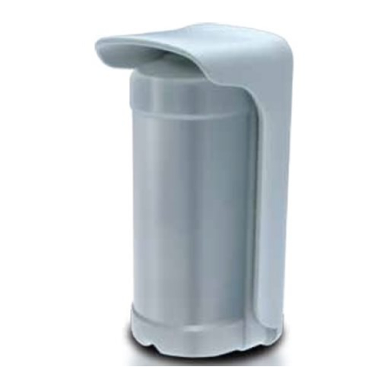
DIRRVE / DIRFE
OUTDOOR DUAL-IR SENSOR
[SMD] [Serie 100] [48bit] [SPV] [AN] [IP54]
DIRRVE / DIRFE is an innovative passive infrared sensor for outdoor use, which has two completely independent and individually adjustable
detection heads. This allows obtaining a great functioning versatility and at the same time, if correctly installed, an excellent decreasing of false
alarms.
The sensor operates with the IR heads in AND mode: it generates alarm only when both IR heads detect intrusion. It is possible to select the
priority of the head which causes alarm.
The two versions are identical concerning functionality and optical settings. They differ from each other just for the alarm transmission mode:
INDEX
1.
TECHNICAL .............................................................................................................................................................................................................................................. 2
2.
PRECAUTIONS ......................................................................................................................................................................................................................................... 3
3.
POWER ON THE SENSOR ......................................................................................................................................................................................................................... 3
4.
BATTERY (ONLY DIRRVE) .......................................................................................................................................................................................................................... 4
4.1. LOW BATTERY ..................................................................................................................................................................................................................................... 4
4.2. BATTERY REPLACEMENT ..................................................................................................................................................................................................................... 4
5.
CORRECT USE OF THE SENSOR ................................................................................................................................................................................................................ 5
6.
HEADS ORIENTATION .............................................................................................................................................................................................................................. 9
7.
AND DIREZIONALE ................................................................................................................................................................................................................................. 10
8.
LIMIT THE DETECTION APERTURE (PARTIAL LENS COVERING) ................................................................................................................................................................ 11
8.1. LENS COVER ..................................................................................................................................................................................................................................... 11
8.2. ADHESIVE MASK ............................................................................................................................................................................................................................... 11
9.
PULSE COUNT ....................................................................................................................................................................................................................................... 12
10.
WALL MOUNTING ............................................................................................................................................................................................................................ 13
11.
SETTINGS ......................................................................................................................................................................................................................................... 16
12.
LEARNING (ONLY DIRRVE) ............................................................................................................................................................................................................... 18
13.
SUPERVISION (ONLY DIRRVE) .......................................................................................................................................................................................................... 18
DIRRVE: RADIO version
"AND" version
Installation and use manual
DIRFE: WIRED version
15.12-M:5.0-H:x.x-F:x.x
Advertisement
Table of Contents

Related Manuals for Duevi DIRRVE


Summary of Contents for Duevi DIRRVE
-
Page 1: Table Of Contents
15.12-M:5.0-H:x.x-F:x.x DIRRVE / DIRFE is an innovative passive infrared sensor for outdoor use, which has two completely independent and individually adjustable detection heads. This allows obtaining a great functioning versatility and at the same time, if correctly installed, an excellent decreasing of false alarms. -
Page 2: Technical
1. TECHNICAL DIRRVE DIRFE POWER SUPPLY n. 2 lithium batteries, 3 V, CR123A type 12 V STAND-BY < 22 µA STAND-BY < 8 mA CONSUMPTION ALARM < 10 mA ALARM < 24 mA AUTONOMY * (estimated) about 2 years with 10 alarms/day + supervision... -
Page 3: Precautions
In particularly difficult environments it’s suggested to set the “pulse count” function to 2 (DIP5 = ON), to increase immunity to false alarms. The estimated battery life of DIRRVE detector is proportional to: • the thermal cycles (heating and cooling) the battery is subject change its capacity and autonomy •... -
Page 4: Battery (Only Dirrve)
4. BATTERY (ONLY DIRRVE) To power the sensor, insert two 3 V lithium CR123A type batteries inside the battery-holder respecting the polarity: Battery-holder Lithium batteries CR123A, 3 V (x 2) Connector Plug the connector of the battery-holder to the terminal on sensor, then insert the battery-holder on the guides:... -
Page 5: Correct Use Of The Sensor
5. CORRECT USE OF THE SENSOR... - Page 6 UPPER IR HEAD Distance (in meters) between IR beams 10 m LOWER IR HEAD 10 m CORRECT POSITION OF THE BEAMS, HEADS WITH 11° OFFSET 11°...
- Page 7 Install the sensor: Height: between 100 cm and 220 cm from the floor Installation surface: vertical (wall or pole) Install protecting visor The beams must be oriented so to end towards ground or against a wall Each detection head is equipped with a Fresnel lens that builds 5 double sectors beams horizontally oriented with a 100°...
- Page 8 To obtain a reliable detection, it is recommended to mount the detector in the way that the intruder crosses beams perpendicularly and not with frontal approach. Crossing of beams: correct Frontal approach: not recommended Fig. 2 – Detection area crossing types Once fixed the detector, to orient the heads, it is recommended to slightly loosen screws closing of joints.
-
Page 9: Heads Orientation
6. HEADS ORIENTATION NO!! The detection heads MUST be oriented to direct the IR beams downwards, NEVER towards the up. Furthermore, the beams must end against a surface (wall, terrain) so to define the detection area e not point towards open space. -
Page 10: And Direzionale
7. DIRECTIONAL AND The “directional AND” function allows to further refine the alarm is generated. This function set the sensor to generate alarm only under a precise detection order of the heads: first the upper head (farther beam) and then, within the AND time, the lower head (closer beam). -
Page 11: Limit The Detection Aperture (Partial Lens Covering)
8. LIMIT THE DETECTION APERTURE (PARTIAL LENS COVERING) Sometimes the heads detection area can be too wide and it can be a potential trouble if in the area to be protected there are tree branches, curtains, windows, etc. In this case, it is possible to reduce the detection area by appropriately masking the lateral or intermediate beams with adhesive tape places over the sectors of the heads lenses (beams blinding), letting them able to detect only the beams oriented towards stable zones of the areas to be protected. -
Page 12: Pulse Count
9. PULSE COUNT By factory settings, the sensor is programmed to give alarm at first intrusion detection (AND of both upper and lower IR heads, “pulse count” = 1). To increase the immunity to false alarms in harsh environment, it is possible to set the “pulse count” to 2 (DIP5 = ON): in this way the sensor will give alarm at the second intrusion detection (each detection is the AND of both upper and lower IR heads). -
Page 13: Wall Mounting
10. WALL MOUNTING Use the visor as mask to mark the position of the holes (A and B) on wall, then drill and insert provided dowels: TAMPER adjustment Insert the TAMPER adjustment screw in the dowel (B) leaving out its head for about 9 ÷ 10 mm from the wall surface. Overlap the visor and the sensor: adjust the TAMPER screw so that fixing the sensor, the switch is pressed without breaking the circuit: About 9 ÷... - Page 14 NOTE FOR THE DIRFE MODEL Before fixing the sensor to the wall, it is necessary to make the cables pass through the appropriate holes. The case has some holes for the cables passage: break one or more (as you need) on the visor (D) and on the sensor base (C): DIRFE Visor Break the holes...
- Page 15 Pass the cable through gland membrane and make connections: Pull wires through the holes and proceed with installation. Cable path Fix the sensor and the visor to the wall (E points matching with A holes) by the three appropriate screws, adding the BLACK o-ring on each, and place the RED o-ring in the appropriate position.
-
Page 16: Settings
11. SETTINGS JUMPER Closed Opened Anti-removal tamper Tamper OFF Tamper ON Anti-opening tamper Tamper OFF Tamper ON Buzzer for test (only with DIP4 = ON) Buzzer ON Buzzer OFF Alarm/transmission LED LED ON LED OFF HEADS RANGE TRIMMER Trimmer to adjust the detection depth of the upper head. Upper head Turn clockwise to increase the detection range. - Page 17 OFF = Alarm with quite time The alarm is generated only if occurs a time gap of more than 30 seconds (quiet time) from a detection DIRRVE: continuous alarm and the other. If within this time another detection occurs, the sensor resets to zero the quiet time. If there is no other DIP6 movement, after this time, the sensor is ready for a new alarm transmission.
-
Page 18: Learning (Only Dirrve)
12. LEARNING (ONLY DIRRVE) To learn DIRRVE detector: Give power supply to detector and wait until the end of starting stabilization (about 30 s) until all LED are off. On the control panel, enter in radio zone learning “by tamper”, ready to receive wireless codes of the detector. - Page 20 This manual may be subject to change without notice...
Need help?
Do you have a question about the DIRRVE and is the answer not in the manual?
Questions and answers