Advertisement
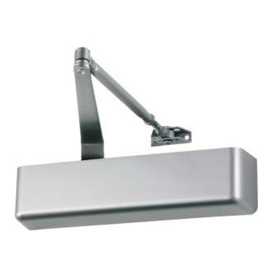
SC71 Series Closer
Installation Instructions
Forged Arm Models, SC71 (1-6 Adj.)
Fasteners
Use
Closer Body
Arm Shoe
Thru-bolt
Fifth Hole
Spacer
Arm
Attachment
Arm
Attachment
Lock Washer
Cover Plug
Cover Screw
L=Latch Speed Valve
S/D=Main Speed Valve
B=Backcheck Valve
Spring Power Adjustment
1
Door and Frame Preparation:
A. Choose degree of door opening.
B. Drill per appropriate fastener, using chart above.
Front View
Right Hand Door Illustrated. Same dimensions
apply for Left Hand Door measured from center
Description
Drill/Tap
#14 Wood
1/8" Drill
1/4-20
#7 Drill, 1/4-20 Tap
#14 Wood
1/8" Drill
1/4-20
#7 Drill, 1/4-20 Tap
Wood/Metal
3/8" Drill
#14 Wood
1/8" Drill
1/4-20
#7 Drill, 1/4-20 Tap
—
—
—
—
—
—
—
—
"P" Valve, Normally Closed
SC71
2³⁄₈"
(60 mm)
6³⁄₄"
(171 mm)
line of hinge.
Closer mounted on push
side of door
(opposite of hinge side).
Improper installation or regulation may result in personal
Spring Power Adjustment
2¹⁄₈"
54 mm
2¹⁄₂"
1¹⁄₁₆"
(64 mm)
27 mm
C L
Hinge
A
1¹¹⁄₁₆"
43 mm
Opening
Up To 100°
8C\v" (222 mm)
101° – 130°
7Z\v" (184 mm)
131° – 150°
6Z\v" (159 mm)
151° – 180°
5Z\v" (133 mm)
CAUTION
injury or property damage. Follow all instructions
carefully. For questions, call Falcon at number below.
(877) 671-7011
L=Latch Speed Valve
S=Main Speed Valve
S/D=Delay Action Valve
B
¹¹⁄₁₆"
17 mm
3³⁄₈"
86 mm
1³⁄₄"
44 mm
A
B
10B\," (270 mm)
9Z\," (232 mm)
8Z\," (206 mm)
7Z\," (181 mm)
SC71 DEL
C L
Hinge
⁵⁄₁₆"
8 mm
Top View
Advertisement
Table of Contents

Related Manuals for Falcon SC71


Summary of Contents for Falcon SC71
- Page 1 1/4-20 #7 Drill, 1/4-20 Tap Improper installation or regulation may result in personal — — injury or property damage. Follow all instructions Attachment carefully. For questions, call Falcon at number below. — — Attachment Lock Washer Cover Plug — —...
- Page 2 48" (1220 mm) — — — — — OR — — — — — Install arm & shoe assembly onto frame. Fifth Hole Spacer SC71 DEL Attach cover with screws. Install closer onto door. Spring tube faces away from hinge Valves UP for Right hand edge.
- Page 3 Cerrador de Puerta Serie SC 71 Ferme-porte Série SC 71 Instrucciones de instalación Instrucions d’installation Modelos con brazos forjados, SC71 (1-6 Adj.) Modèle à bras forgé, SC71 (1-6 Adj.) Sujetadores Aplicación Descripción Perfore/ Roscas Ferrures D'application Description Percez/ Taraud Cerrador montado al lado...
- Page 4 42" (1050 mm) 48" (1220 mm) 48" (1220 mm) Instale el ensamblaje del Installez l’assemblage du brazo. bras. SC71 DEL Sujeta la tapa con las Fixez le couvercle avec les Espaciador para el quinto agujero tuercas. vis. Espaceur du cinquième trou...
- Page 5 Release Date White Paper D. Myers M. Sasso 047232 02-17-14 Notes Title 1. printed two sides SC71 Series Forged Arm Instruction Sheet 2. printed black Creation Date Number Revision 3. tolerance ± .13 01-03-12 4. printed in country may vary 43722 5.
Need help?
Do you have a question about the SC71 and is the answer not in the manual?
Questions and answers