
Subscribe to Our Youtube Channel
Related Manuals for Falcon 8230-3454


Summary of Contents for Falcon 8230-3454
- Page 1 Installation Instructions Falcon Electro-mechanical Swing Operator Models: 8230 & 8240 640072-00(C) © 2012 Ingersoll-Rand Company Limited Phone: 1-877-671-7011...
-
Page 2: Replacement Parts & System Components
The activating circuit opens the door from any position in the closing swing. During a power failure, the Falcon Operator acts as a manual door closer (Size 3). Door opening and closing cycles, including opening speed, back check speed, hold open time delay, closing speed, latch position, and backcheck position are adjustable. -
Page 3: Pre-Installati On Site & Product Check
1. PRE-INSTALLATI ON SITE & PRODUCT CHECK Check that the product model is correct for the required application. Check that all parts listed on the Bill of Material are in the shipping container. Check the architectural drawings and final approved shop drawings for the position of frame and structural openings. - Page 4 2. OPERATOR INSTALLATION Remove Control Box from Operator Mounting Bracket, then remove Motor/Gearbox from Bracket: 26” Pull, 26” Push 1/4” - 20 Remove screw to remove control box from mounting bracket Prepare Header/Frame and Door: 26” Pull System ......See below ”...
- Page 5 2. OPERATOR INSTALLATION (CNTD) 26” Push System Header/Frame and Door Preparation 8” 6” Control Gearbox 1-3/16” 5/8” Drop Mount Application (26” Push System Only) Header/Frame and Door Preparation 6” 8” Page 5 of 12...
-
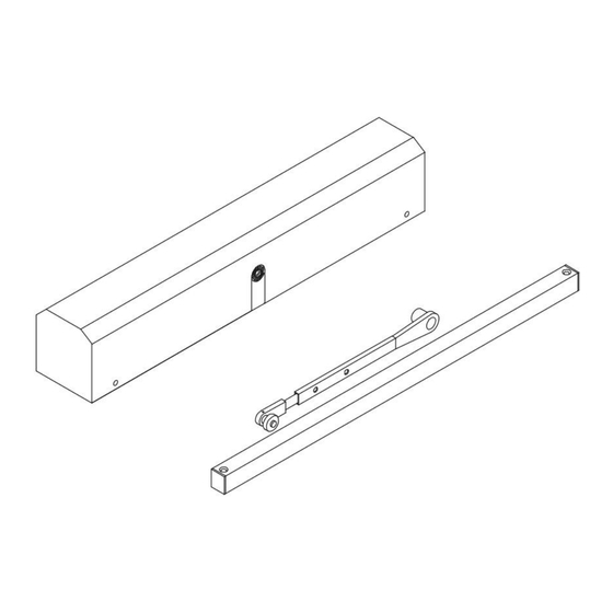
Page 6: Arm & Cover Installation
3. WIRING CAUTION Make sure all wires are properly dressed and secured to prevent interference Route all wiring away from moving parts, sharp edges, and heat sources Use copper conductors only Do not modify the factory wiring or connect into existing electrical circuits or devices Refer to the appropriate wiring diagram for the Control Box (page 12 ) or the diagram supplied for custom applications. - Page 7 4. ARM & COVER INSTALLATION (CNTD) Pull Arm Installation 4.5.1 Slide the pull arm roller into the track, then insert a track end cap on each end of the track and install track to door. 4.5.2 Attach the Pull Arm to the track roller with the roller locking screw and to the operator spindle loosely with the 8mm socket head screw.
-
Page 8: Operational Check
5. OPERATIONAL CHECK Activate the operator using the activation device. The operator will perform one sizing cycle. Sizing Cycle: Occurs after power is turned on and a legitimate activation signal is received. During the sizing cycle, the door opens and closes one time. If the door does NOT OPEN AT ALL during the sizing cycle: •... -
Page 9: Operator Adjustment
6. OPERATOR ADJUSTMENT See table below and diagrams (page 10 ) for operator feature adjustment. After adjusting, cycle the door several times to check for proper operation. NOTE Adjust Operator for the SLOWEST operation practical, in accordance with the latest revisions of the Americans with Disabilities Act (ADA);... - Page 10 6. OPERATOR ADJUSTMENT (CNTD) Push Main Back Back Fuse Open Close Latch Hold Check Check Power Delay Speed Speed Open Power Motor Speed Fuse 12 VAC Page 10 of 12...
-
Page 11: Release For Service
Provide the owner or person in charge with a contact name and phone number to call for future service and maintenance. IMPORTANT Be sure to install all Safety, Traffic Control and Instruction Labels onto the door, as required 8. FALCON SOFTWARE Operation: 8.1.1 Sizing From start-up (Sizing), the door will activate via: Main Input (Main Act and Main Act Com). - Page 12 8. FALCON SOFTWARE (CNTD) 8.1.2 Standard Operation Upon a legitimate activation signal, the door accelerates to opening speed while monitoring the current load on the drive output. If the current exceeds the specified level, the door will stop and close.
Need help?
Do you have a question about the 8230-3454 and is the answer not in the manual?
Questions and answers