Table of Contents

Related Manuals for Cisco 450


Summary of Contents for Cisco 450
- Page 1 Cisco 450 Voice Gateway Hardware Installation Guide First Published: 2018-10-15 Americas Headquarters Cisco Systems, Inc. 170 West Tasman Drive San Jose, CA 95134-1706 http://www.cisco.com Tel: 408 526-4000 800 553-NETS (6387) Fax: 408 527-0883...
- Page 2 © 2018 Cisco Systems, Inc. All rights reserved.
-
Page 3: Overview Of Cisco Vg450 Voice Gateway
Platform and Software Requirements, on page 8 Features and Benefits of Cisco VG450 Voice Gateway Cisco VG450 Voice Gateway provides VoIP connectivity to analog devices, such as analog desk phones, analog conference room phones, fax machines and modems. Cisco 450 Voice Gateway provides several... - Page 4 Overview of Cisco VG450 Voice Gateway Features and Benefits of Cisco VG450 Voice Gateway service modules can be inserted into the SM-X slot on the supported Cisco 4000 Series ISRs without powering off the router. • FXS-E (extended loops) support—FXS ports on the new modules support FXS-E with the following details: •...
-
Page 5: Analog Phone Connectivity
Feature Access Codes (FACs) for invoking supplementary services. Fax and Modem Connectivity FXS ports on Cisco 450 Voice Gateway support fax machines and modems. When using fax machines, the gateways support T.38 fax relay and fax pass-through. T.38 fax relay technologies allow transfer of faxes across the network with high reliability using less bandwidth than a voice call. -
Page 6: Slot, Bay, And Ports
The FXS port is used to connect analog phones, modems, fax machines, and speaker phones to an enterprise IP voice system, and to use them as extensions to your Cisco or third-party IP call-control system. Having these devices tightly integrated with the IP-based phone system is advantageous for increased manageability, scalability, and cost-effectiveness. - Page 7 • 16 for 72FXS mode • 40 EN LED (Amber/Green) — • 56 for 56FXS-E mode • 30 ACT LED (Green) The slot, bay, and port information for Cisco 450 Voice Gateway FXS module is as follows: Interface Slot Port SM-X-8-FXS/12FXO SM-X-16-FXS/2FXO 0-15...
-
Page 8: Cisco Vg450 Voice Gateway Chassis
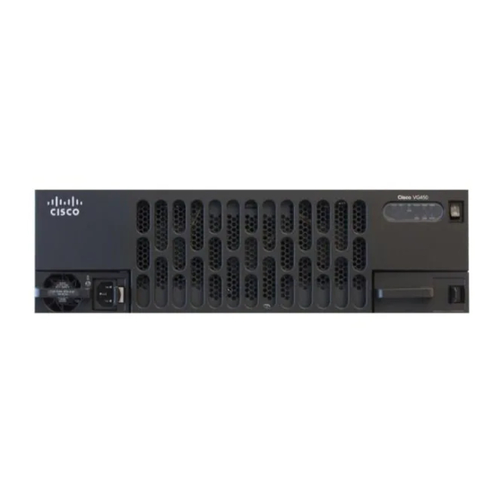
24-27 Cisco VG450 Voice Gateway Chassis The following figures show the front and back panels of the Cisco VG450 Voice Gateway Chassis: Figure 1: Front Panel of the VG450 Voice Gateway Figure 2: Back Panel of the VG450 Voice Gateway Technical and Compliance Specifications The following table details the technical specifications of Cisco VG450 Voice Gateway. - Page 9 Cables Category 3 and Category 5 Category 3 and Category 5 Category 3 and Category 5 Category 3 and Category 5 The following table details the compliance specifications of Cisco VG450 Voice Gateway. Cisco 450 Voice Gateway Hardware Installation Guide...
-
Page 10: Platform And Software Requirements
• EN300-386 Platform and Software Requirements Cisco 450 Voice Gateway is supported on Cisco 4461 Integrated Services Router effective with Cisco IOS XE Fuji 16.9.1 or later. The service modules provide gateway services for Cisco Unified Communications using Cisco Unified Communications Manager with SRST or Cisco Unified Communications Manager Express. -
Page 11: Configuration Methods
Overview of Cisco VG450 Voice Gateway Configuration Methods Configuration Methods After Cisco 450 Voice Gateway is operational, use the procedures in Cisco Voice 450 Gateway Software Configuration Guide to configure the specific services and functions or to make changes to an existing configuration. - Page 12 Overview of Cisco VG450 Voice Gateway Configuration Methods Cisco 450 Voice Gateway Hardware Installation Guide...
-
Page 13: Planning Your Installation
Enclosed racks must have adequate ventilation. An enclosed rack should never be overcrowded and should have louvers and a fan. If the Cisco VG450 Voice Gateway is installed in an enclosed rack with a ventilation fan at the top, make sure that heated air drawn upward from other equipment does not prevent adequate cooling. -
Page 14: Access To Chassis
(due to prevalence of UPS for personal computers). Thus, a separate UPS for Cisco VG450 Voice Gateway is a viable option when the ISR/UPS is not co-located with it. If you suspect that your AC power is not clean—if lights flicker often or there is machinery with large motors nearby—have a qualified person test the power. -
Page 15: Distance Limitations For Interface Cables
Statement 1017 Cable Types The cable types that are used are dependent on the Cisco VG450 Voice Gateway that you are using. For more information, see the “Cable Specifications and Information”... -
Page 16: Interference Considerations
• Strong electromagnetic interference (EMI), especially as caused by lightning or radio transmitters, can destroy the EIA/TIA-232 drivers and receivers in the Cisco VG450 Voice Gateway. If you use twisted-pair cables with a good distribution of grounding conductors in your plant cabling, emitted radio interference is unlikely. -
Page 17: Installing The Cisco Vg450 Voice Gateway
1030 Danger Read the installation instructions before connecting the system to the power source. Statement 1004 This chapter contains the procedures for installing your Cisco VG450 Voice Gateway and consists of the following sections: • Safety Recommendations, on page 15 •... - Page 18 This equipment must be grounded. Never defeat the ground conductor or operate the equipment in the absence of a suitably installed ground conductor. Contact the appropriate electrical inspection authority or an electrician if you are uncertain that suitable grounding is available. Statement 1024 Cisco 450 Voice Gateway Hardware Installation Guide...
- Page 19 To report a gas leak, do not use a telephone in the vicinity of the leak. Statement 1039 Danger Before opening the unit, disconnect the telephone-network cables to avoid contact with telephone-network voltages. Statement 1041 Cisco 450 Voice Gateway Hardware Installation Guide...
-
Page 20: General Safety Practices
• Look carefully for possible hazards in your work area, such as moist floors, ungrounded power extension cables, and missing safety grounds. • If an electrical accident occurs, proceed as follows: • Use caution; do not become a victim yourself. • Turn off power to the system. Cisco 450 Voice Gateway Hardware Installation Guide... -
Page 21: Preventing Electrostatic Discharge Damage
The folllowing Installation Checklist lists the tasks for installing a Cisco VG450 Voice Gateway. Print a copy of this checklist and mark the entries as you complete each task. For each Cisco VG450 Voice Gateway, include a copy of the checklist in your Site Log. (Installation Checklist image) -
Page 22: Mounting Tools And Equipment
Initial operation verified Mounting Tools and Equipment Obtain the following tools and parts to install a Cisco VG450 Voice Gateway: • Standard flat-blade screwdriver as required for attaching brackets to rack or wall • Phillips screwdriver for attaching brackets to a Cisco VG450 Voice Gateway •... -
Page 23: Unpacking And Inspection
• Modem for remote configuration Unpacking and Inspection Do not unpack the Cisco VG450 until you are ready to install it. If the installation site is not ready, keep the chassis in its shipping container to prevent accidental damage. The Cisco VG450, cables, printed publications, and any optional equipment you ordered might be shipped in more than one container. - Page 24 (OIR) commands. Leave the power cable plugged in to channel ESD voltages to ground. For more information on OIR, see the “Managing Cisco Enhanced Services and Network Interface Modules” chapter in the Cisco 4000 Series ISRs Software Configuration Guide .
- Page 25 Installing the Cisco VG450 Voice Gateway Removing Cisco VG450 Voice Gateway If you are not replacing the module, install a blank faceplate over the empty slot to ensure proper air flow. Cisco 450 Voice Gateway Hardware Installation Guide...
- Page 26 Installing the Cisco VG450 Voice Gateway Removing Cisco VG450 Voice Gateway Cisco 450 Voice Gateway Hardware Installation Guide...
-
Page 27: Checklist For Power-On
• Troubleshooting, on page 27 Checklist for Power-On You can power on a Cisco VG450 Voice Gateway if it meets the requirements described in Chapter 3: Installing the Cisco VG450 Voice Gateway. • The chassis is securely mounted. • Power cable is connected. - Page 28 Powering On the Cisco VG450 Voice Gateway Power-On Procedure 2. Move the Cisco VG450 Voice Gateway power switch to the ON position. 3. Enter no to proceed with manual configuration using the CLI: 4. Press Return to terminate autoinstall and continue with manual configuration.
-
Page 29: Troubleshooting
If the rommon 1> prompt appears, your system has booted in ROM monitor mode. For information on the Note ROM monitor, refer to the router rebooting and ROM monitor information in the Cisco IOS Configuration Fundamentals Configuration Guide for your Cisco IOS software release. - Page 30 Possible Cause Corrective Action Reset/replace console Console screen display freezes Console fault Software error Repeat power-on procedure Faulty Cisco VG450 Contact Cisco 1 or your Cisco reseller See the “Obtaining Technical Assistance” section. Cisco 450 Voice Gateway Hardware Installation Guide...
-
Page 31: Cable Specifications And Information
Console and Auxiliary Port Cables and Pinouts Your Cisco VG450 Voice Gateway comes with the cable and adapters you need to connect a PC, an ASCII terminal, or a modem to your Cisco VG450 Voice Gateway. The cable kit includes: •... -
Page 32: Console Port To Ascii Terminal
RJ-45 Pin DB-9 Signal Pin 1 is connected to pin 8 inside the Cisco VG450 Voice Gateway. Console Port to ASCII Terminal Figure A-2 shows the RJ-45-to-RJ-45 rollover cable assembly and the RJ-45-to-DB-25 female DTE adapter (labeled TERMINAL); Table A-2 lists the pinouts. -
Page 33: Auxiliary Port To Modem
RJ-45 Pin DB-25 Signal Pin 1 is connected to pin 8 inside the Cisco VG450 Voice Gateway. Auxiliary Port to Modem Figure A-3 shows the RJ-45-to-RJ-45 rollover cable assembly and the RJ-45-to-DB-25 male DCE adapter (labeled MODEM); Table A-3 lists the pinouts. -
Page 34: Alternative Connections To Terminal And Modem
Alternative Connections to Terminal and Modem Your Cisco VG450 Voice Gateway ships with an RJ-45-to-RJ-45 rollover cable and two adapters for connection to a PC, a terminal, or a modem. If you want to use an RJ-45 straight-through cable or other adapters, see Table A-4 for usable cable and adapter combinations. -
Page 35: Analog Voice Multiport Pinouts (Rj-21X/Ca21A)
– RX– – – Any pin not referenced is not connected. Analog Voice Multiport Pinouts (RJ-21X/CA21A) Figure A-5 shows the RJ-21 connector wiring for the cable used for the multiport analog voice interface. Cisco 450 Voice Gateway Hardware Installation Guide... - Page 36 RingTip RingTip 1843 RingTip RingTip 1944 RingTip RingTip 2045 RingTip RingTip 2146 RingTip 1035 RingTip 2247 RingTip 1136 RingTip 2348 RingTip 1237 RingTip 2449 RingTip — — — — 25, 50, 51, 52 Cisco 450 Voice Gateway Hardware Installation Guide...
Need help?
Do you have a question about the 450 and is the answer not in the manual?
Questions and answers