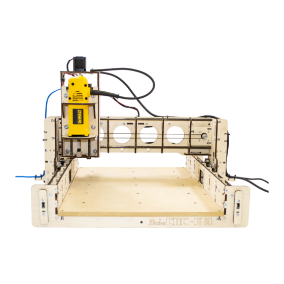
BobsCNC E3 Assembly Manual
Cnc engraver
Hide thumbs
Also See for E3:
- Troubleshooting manual (16 pages) ,
- Manual (9 pages) ,
- Quick start manual (3 pages)
Table of Contents
Advertisement
Advertisement
Table of Contents

Related Manuals for BobsCNC E3


Summary of Contents for BobsCNC E3
- Page 1 Assembly Manual Version 2.15 Page 1...
-
Page 2: Table Of Contents
Safety First Getting Started ······························································································· 5 Required Tools Good Ideas For More Information E3 Hardware Parts Guide ················································································ 6 Z-Spindle Mount Assembly Instructions ························································ 7-17 Wood Components (included with the kit) Required Hardware (included with the kit) Illustrated Steps Y Carriage Assembly Instructions ··································································· 18-37... -
Page 3: Table Of Contents
Installing the Belts ·························································································· 70-74 Wood Components (included with the kit) Required Hardware (included with the kit) Illustrated Steps Installing the Spoilboard ················································································· 75-76 Initial Setup ··································································································· 76-79 Tips to Keep Your Controller from being Damaged ········································· 80-81 GRBL and Universal G Code Sender Software·················································· 82 Quick Start Guide ····························································································... -
Page 4: Specifications
Cutting Area: 17.7" (450 mm) 15.3" (390 mm) 3.3" (85 mm) The complete E3 parts list can be found in the appendix. Safety is your responsibility. Use the proper protective equipment and "safety sense" when building and operating your CNC Router. -
Page 5: Getting Started
Multimeter to correctly connect the power supply and stepper motors. A multimeter is also a good tool to have for general electronic trouble shooting. *Look for Good Ideas • We recommend using a large flat, clean working surface for assembling your E3. • All screws (unless noted) should be installed snug, then rotated one 1 to 2 1/2 turns. - Page 6 Caution: This kit includes small parts that are a choking hazard for small children. Prior and during assembly keep all parts out of the reach of small children. CAUTION E3 Parts Identification 2mm Allen Wrench 1.5mm Allen Wrench M3 x 10 M2.5 x 16...
-
Page 7: Z-Spindle Mount Assembly Instructions
Z-Spindle Mount Assembly Instructions Z-Spindle Mount Wood Components Part # Component Frame Mount Support Z-Frame Support Z Frame Z-Spindle Bottom Mount Z-Spindle Top Mount Z-Spindle Mount Hardware Part # Qty Hardware Description Coupler Nut Threaded Rod 5/16” Washers M4 Nut M4 x 16 Screws 6mm Hardened Washers SG20U Bearings... - Page 8 It is a good idea to apply dry lube to the threaded rod once a month . Dry lube is a good lubricant for the dusty environment created when operating Your E3 CNC. Thread the Coupler Nut on the threaded rod in the order Step 2 as shown below: steel washer >...
- Page 9 Position second Z Frame Support on top of the washer Step 4 and nut assembly. Set tabs of Z Frame Supports in the corresponding Step 5 Z Frame slots. (The assembly should look like this). Page 9...
- Page 10 Secure Assembly components with six M4 x 16 Screws Step 6 and Nuts. Apply LOCTITE to all screws. All screws (unless noted) should be installed snug, then rotated 1 to 2 1/2 turns. Position the nut in “T” of the T-Slot before inserting screws and tightening.
- Page 11 Place the Z Spindle Bottom Mount into the Z Frame and Step 8 secure with five M4 x 16 Screws and Nuts as shown below. Page 11...
- Page 12 Step 9 Preparing the DeWalt 660 Rotary Tool for Mounting (see next page for step by step instructions). Page 12...
- Page 13 Step by Step Instruction for preparing the DeWalt 660 Remove guide base assembly. Remove the Collet Nut. 1. Press and hold down the Spindle Lock. 2. Use wrench to loosen Collet nut. 3. Remove Collet nut (do not discard the collet or the collet nut). Remove the Spindle Cover 1.
- Page 14 Step 10 Place Z Spindle Top Mount over the DeWalt and slide into position. The Top Mount must be compressed into the correct position so that the slots on the frame are aligned with the Top Mount tabs. Note the position of the cord stress relief ( to the left) The DeWalt name plate will facing up.
- Page 15 Step 11 Using a M4 Star Driver, reinsert the four original DeWalt screws through the mount into the DeWalt as shown below: Step 12 Place the Frame Mount Supports into the Z Frame and secure both sides with three M4 x 16 screws and nuts (see below): Page 15...
- Page 16 Step 13 Secure the Z Spindle Top Mount with two M4 x 16 screws and nuts as shown. Step 14 Install two SG20U bearings with the M6 x 25 screws, 6mm washers and M6 nuts. The bearing hubs must face the wood as illustrated below The screws in the round holes should installed snug, then rotated two to four turns.
- Page 17 Step 15 Insert and move the two remaining SG20U bearings in the slotted holes (photo below right) inward and snug the nuts then rotate 1/4 turn. The nuts will be tightened later when the installed on the Y Carriage. Completed Spindle Mount Assembly (back view): Completed Spindle Mount Assembly (front view): Page 17...
- Page 18 Y Carriage Mount Assembly Instructions Y Carriage Wood Components Part # Qty Component Z Stepper Motor Mount Bearing Bottom Plate Bearing Top Plate Bearing Middle Plate Y Carriage Frame Y Carriage Side Support Belt Retainer Z-Rail Stop Z-Rail Support Y Carriage Hardware Y Carriage Bottom Support G H I Part #...
- Page 19 Try placing 1” strips of blue painters tape behind the T-Slots to help hold the nuts in place. All screws (unless noted) should be installed snug, then rotated 1-1/2 to 2 turns. Step 1 Place Z Carriage Rail Support into the Y Carriage Frame and secure with three M4 x 16 screws and nuts (see below): Step 2 Place second Z Carriage Rail Support into the Y Carriage Frame...
- Page 20 Step 3 Attach Y Carriage Side Support and secure with five M4 x 16 screws and nuts. Step 4 Attach second Y Carriage Side Support and secure with five M4 x 16 screws and nuts. Page 20...
- Page 21 Step 5 Attach Y Carriage Bottom Support and secure with five M4 x 16 screws and nuts. Page 21...
- Page 22 Step 6 Attach Z Rail Stop and secure with two M4 x 16 screws and nuts. Page 22...
- Page 23 Step 7 Attach both Belt Retainers and secure with six M4 x 16 Screws and Nuts. Be sure the tooth profile is on the top, smooth profile bottom (see photo below). Page 23...
- Page 24 Step 8 Install four SG20U Bearings using M6 x 25 screws and nuts . Make sure the hub of the bearing faces the wood. IMPORTANT: the screw must be oriented so that the nut is visible when looking at the back of the carriage (see photo below).
- Page 25 Notice that the two round and two elongated holes in the Y Carriage Frame (left photo): round holes Insert screw through the hardened washer then through the plywood hole. Next put second washer on the screw then the bearing with the hub against the washer. Last, thread the nut on the screw and snug, the rotate two to four turns Page 25...
- Page 26 The finished installation of the bearings should look like this: The Bearings in the round holes (on top) must be tight. Bearings in the elongated holes should be snug and then rotate 1/4 turn. Page 26...
- Page 27 Step 9 Gently insert the two 7 1/8” x 5/16” rods through the Z Rail Supports and into holes in the Y Carriage Bottom Support. Rotate the rails through the Z Rail supports. Do not “snap” them into place. Page 27...
- Page 28 Step 10 Attach Z-Drive to Y Carriage. Slide Z-Assembly Bearings over the Z-Rails. DO NOT FORCE! The SG20U Bearings should roll firmly. There should be a small amount of preload. If the Z Assembly doesn’t gently of slide onto the rails or if the assembly sets loosely on the rails: •...
- Page 29 Step 11 Slide Bearing Bottom Plate over the Threaded Rod setting tabs in slots. Step 12 Attach the Bearing Bottom Plate and secure with four M4 x 16 Screws and Nuts. Page 29...
- Page 30 Step 13 Attach 5/16 Nuts and Bearing on Threaded Z-Rod As the Router travels up and If necessary down the Z Axis make sure adjust to center the Threaded Z-Rod remains the rod. center in the hole. Thread 5/16 nut on Threaded Z-Rod Page 30...
- Page 31 Slide 8 x 22 x 7 Bearing on Threaded Rod. Thread 5/16 Nut on top of the Bearing. Page 31...
- Page 32 The 5/16 Nut on top of the bearing should be turned approximately 6 threads down from end of the Z-Rod. The bearing should be tightened firmly against the upper nut while maintaining the six thread spacing from the end of the threaded rod.
- Page 33 Step 14 Secure Bearing with Bottom, Middle, and Top Bearing Plates. Slide Z-Spindle Mount down rails until nut and bearing assembly rests on Bearing Bottom Mount. Slide Middle Bearing Plate over the Threaded Rod and Bearing. Page 33...
- Page 34 Slide Top Bearing Plate over the Threaded Rod and Bearing and secure with three M4 x 25 Screws and M4 Nuts. In order to properly retain the bearing securely, evenly tighten screws and nuts in a rotating pattern so that the plywood components are compressed uniformly and tightly together.
- Page 35 Step 15 Attach Stepper Motor to the Stepper Motor Mount and secure with four M3 x 10 screws. Apply LOCTITE to all screws. Page 35...
- Page 36 Attach Helical Coupler to Stepper Motor Step 16 shaft and Threaded Z-Axis Rod Align the milled flat spot on the end of the Threaded Z- Rod so that the set screw will be tightened directly against the flat spot. Tighten both set screws with a 2mm Allen Wrench.
- Page 37 Secure Stepper Motor Mount with four M4 x 16 Screws and Nuts. Page 37...
-
Page 38: Frame Assembly Instructions
Frame Assembly Instructions X Frame Assembly & Hardware A. M4 x 16 Screws (52) Part # Qty Component Part # Qty Hardware Description B. M4 x 16 Nuts (52) X Rail Support 52 M4 x 16 Screws 52 M4 Nuts Frame Corner Brace X Rail Stop Frame Mid Support... - Page 39 Place the four X Rail Supports onto the Frame Side Step 1 Support and secure each with three M4 x 16 Screws and Nuts. Repeat procedure with the remaining four X Rail Supports Step 2 and second Frame Side Support and secure each with three M4 x 16 screws and nuts.
- Page 40 Place both Frame Side Assemblies onto the two Frame Step 2 Mid Supports and secure with four M4 x 16 screws and nuts. The Frame Side Rails will have the same orientation as shown. Page 40...
- Page 41 Place the four Frame Corner Brace tabs into the Step 3 corresponding slots as shown and Secure with one M4 X 16 Screw and Nut. Page 41...
- Page 42 Attach both Frame End Supports and secure each Step 4 with eight M4 x 16 Screws. The four X3 Rail Stops will be used in a latter step. Page 42...
-
Page 43: Gantry Assembly Instructions
Gantry Assembly Instructions Gantry Wood Components & Hardware Part # Qty Description Part # Qty Description Gantry Frame M4 x 16 Screws Gantry Side Support M4 Nut Gantry Corner Brace M4 x 25 Screws Y Rail Supports M6 Nuts Controller Mount M6 Hardened Washers Y Rail Stop M6 x 25 Screws... - Page 44 In order to properly complete the next step all five parts must be assembled before attempting to secure them with M4 x 16 screws and nuts. Position the Controller Mount, the two Gantry Main Step 1 Braces and the two Gantry Back Supports and secure with twenty M4 x 16 screws and nuts.
- Page 45 IMPORTANT Note the orientation of the Controller Mount below: Page 45...
- Page 46 Using slots and tabs, set the Controller Mount Assembly on the Gantry Frame. Page 46...
- Page 47 Secure the Controller Mount Assembly to the Gantry Frame using sixteen M4 x 16 screws and nuts. IMPORTANT Note the orientation of the Controller Mount below. Note that the hole in the Gantry Frame is accessible because of the cutout in the Controller Mount.
- Page 48 Flip the Gantry Main Frame over and insert the five Step 2 Y Rail supports to the Gantry Assembly and secure each with three M4 x 16 Page 48...
- Page 49 Attach Y Stepper Motor Mount and secure with a M4 x Step 3. 16 screws and nuts. Stepper Motor Mount Page 49...
- Page 50 Attach Idler Mount and secure with a M4 x 16 screw and Step 4 nut. Page 50...
- Page 51 Attach both Gantry Side Frames and secure each with Step 5 six M4 x 16 screws and nuts (each side). Do not install the two fasteners that connect the Gantry Side Frame at this time. Two M4 x 25 Screws with nuts will be inserted in each piece in a later step: Page 51...
- Page 52 Attach both Gantry Corner Braces and secure each with Step 6 two M4 x 16 screws and nuts. Page 52...
- Page 53 Install four SG20U bearings on the inside of both Gantry Step 7 Sides Frames. Snug the bearings in the round holes then rotate two to four turns. Gantry Bearing sequence: Screw head / SG20U Bearing (hub inboard)/ Hardened Washer/Plywood / Hardened Washer /Nut Page 53...
- Page 54 Move the SG20U Bearings in the elongated holes Step 8 upward and snug the nuts and rotate 1/4 turn. These will be tightened when installed on the Main Frame. Install three sets of Idler Bearings by inserting a M5 x 25 Step 9 Screw into the Flanged Bearings (keeping the flanges outboard).
- Page 55 Left Side Right Side Location of Idler Bearings Add Gantry Side Brace and Side Support and secure with Step 10 seven M4 x 16 screws and nuts. Repeat for other side. The G13 Cable Mounts will be installed in a later step (p 76). Page 55...
- Page 56 Gantry Assembly and GT2 Pulley Instructions Parts Required Part # Qty Description Assembled Gantry Stepper Motors Switches Controller 10 Small Zip Ties GT2 Pulleys Spiral Wrap M42.5 x 16 M3 x 10 Screws M2.5 Nuts Install each of the three Stepper Motors and secure Step 1 each with four M3 x 10 Screws.
- Page 57 Carefully label each Stepper Motor connector so that the correct electrical connections will be made to the controller (see below): Stepper Motor mounting viewed from the back side: Y Stepper Motor X2 Stepper Motor X1 Stepper Motor Insert each of the three GT2 Pulleys into position and Step 2 tighten the set screws.
- Page 58 Install the X and Y Stepper Motor Home Switches on the Step 3 same side of the Gantry, secure each with two M2.5 x 16 Screws and Nuts in the orientation as shown below (Do not over tighten). Mark each Home Switch connector so that you will be able to make the proper connection to the controller.
- Page 59 Carefully wrap the wires with Spiral Wrap then gently Step 4 route them. There are different ways to route the wires, what important is that the wires are properly wrapped and Secured. To avoid false triggering the X, Y and Z Home Switches caused by the electrical noise of the Stepper Motor wires, it is a best practice to secure the Home Switch wires with Spiral Wrap every 5 or 6 turns as shown below: Excess wire can be bundled, then wrapped to...
- Page 60 Page 60...
-
Page 61: Gantry Installation Instructions
Gantry Installation Instructions Gantry Wood Components & Hardware Gantry Assembly Frame Assembly 4-Long Rods 4-X Rail Stops 8-M4 x 16 screws 8-M4 x 16 nuts Place two of the X Rail Stops and secure each with two Step 1 M4 x 16 screws and nuts (these will be thoroughly tightened after the GT2 Drive Belts are installed. - Page 62 Step 2 Position Gantry gently over the Main Frame. Step 3 Carefully insert the upper rods through the Main Frame and under the upper pair of SG20U Bearings, through each of the X Rail supports until the end of the rod is seated in the Frame End Mounts .
- Page 63 Step 4 Carefully insert the lower rods through the Main Frame and over the bottom pair of SG20U Bearings, through each of the X Rail supports until the end of the rod is seated in the Frame End Mounts. As the SG20U Bearings roll across the rod there should be a small amount of preload (i.e., they should securely engage the rail and roll firmly).
- Page 64 If any of the bearings rotate without engaging the rail: • Remove both of the X rods • Loosen the 2 nuts on the slotted holes on each side & slide the SG20U bearings upward • Snug the SG20U bearing nuts •...
-
Page 65: Y Carriage Installation Instructions
Y Carriage Installation Instructions Part # Qty Description Part # Qty Description Parts Required: Gantry & Frame Assembly M4 x 25 Screws Y Carriage Assembly M4 x 25 Nuts Y Rail Stops 8mm Rods Switches Spiral Wrap M2.5 x16 Screws M2.5 Nuts Page 65... - Page 66 Step 1 Insert the top rod through the Gantry Side and carefully through the Y Rail Supports into the opposite Gantry Side. Step 2 Carefully hang the upper bearings of the Y Carriage assembly onto the rod. Next, insert the bottom Y Rail through the Gantry Side and over the lower set of bearings and through the Y Rail Supports into the opposite Gantry Side.
- Page 67 As the SG20U Bearings roll across the rod there should be a small amount of preload (i.e., they should securely engage the rail and roll firmly). Check the upper bearings to ensure that they are snug up against the rail. The bearing should move along the rail when rotated by hand.
- Page 68 Step 5 Attach the Z-Home Switch to the side of the Y Carriage Side Support and secure with two M2.5 x 16 screws and nuts. Do not overtighten the M2.5 x Screws and Nuts when attaching a switch. Overtightening can cause the switch to fail.
- Page 69 Step 6 Spiral wrap the Switch Wires and zip tie the wrapped wires as shown. Make certain that the Y Carriage Assembly moves freely from one end to the other on the Rails without binding the wrapped/bundled wiring. Page 69...
-
Page 70: Installing The Belts
Installing the Belts Parts for assembly include: 1-Engraver assembly 2 -X belts 1-Y belt 4-Nylon ties Route the X-Belt through the top of the Frame End Support and Step 1 the top slot of the X-Rail Stop slot as shown leaving approximately 2 inches. - Page 71 These photos illustrate how the belt wraps around the GT2 Pulley and Idler. Page 71...
- Page 72 Step 3 Pull the belt through the lower slot on the X-Rail Stop. While keeping the belt taut, push the X Rail Stop downward to trap the belt. Tighten the M4 x 16 screws. Be careful not to overtighten the belt. There should be no more than 1”...
- Page 73 Step 5 Route the Y Belt into the Belt Retainer as shown. Step 6 Route the loose end of the Y Belt around the GT2 Pulley and Idler and secure the loose end into the other Belt Retainer. (Be sure the teeth on the Belt engage the teeth on the GT2 Pulley.) Page 73...
- Page 74 Step 7 Tighten the belt by moving the Idler and tightening the Idler screw and nut. Shorten belt if needed (see below): Page 74...
-
Page 75: Installing The Spoilboard
Installing the Spoilboard Parts for assembly include: 1-Engraver assembly 1 Spoilboard 8-M4 x 16 screws 8-M4 nuts Step 1 Place M4 nuts into the slots on the Frame End and Frame Mid Support. Step 2 Gently set the Spoilboard into position. Be sure the thread insert flanges face down). -
Page 76: Initial Setup
Step 3 Measure and align the front edge of the Spoilboard to ensure the Frame is square, then secure with eight M4 x 16 screws. Initial Setup Step 1 Connect the wire mounts on each side and secure with two M4 x 16 Screws and Nuts as shown below: Page 76... - Page 77 Step 2 Secure the Controller with 4 Small Zip Ties as shown. Be careful not to overtighten which can damage the Controller. Page 77...
- Page 78 Step 3 Attach USB cable to controller as shown. Step 4 Loop USB cable from the Controller and secure to Gantry Frame with Small Zip Ties. Page 78...
- Page 79 Step 5 Route the Power Supply as shown, connect to Controller and secure in place with Small Zip Ties. Page 79...
-
Page 80: Tips To Keep Your Controller From Being Damaged
Tips to keep your controller from being damaged. Always unplug the power supply when connecting of disconnecting the • stepper motor connectors. Make sure all 4 pins are connected for each stepper motor. It is really easy • to get the connector offset by one pin. Check and double check your connections before applying power to the •... - Page 81 Make sure the Negative (-) is connected to the white or black wire and the Positive (+) is connected to the red or blue wire. Incorrect connections will damage the controller. Note that the X1 Stepper orientation is opposite the others. (the red wire is on the left in the diagram and picture).
-
Page 82: Quick Start Guide
GRBL and Universal G-code Sender Software • Version 1.1e of GRBL has been uploaded to the controller. • There are several G-code senders for GRBL. I have had success with the Universal G-code Sender Platform Version • Some of the firmware values can be changed from the G-code sender software. Below is a table for the default values uploaded into the firmware from GRBL 1.1e. - Page 83 Please check BobsCNC.com for the latest copy. Axis Definitions and Home Location The engraver is setup using the right-hand coordinate system. The arrows in the diagram below displays the positive direction for both the X and the Y axis.
- Page 84 The E3 kit includes clamping hardware. Insert the wing nut onto the 2” ¼-20 screw as shown. The screws will thread into the inserts on the table. The extra clamps can be used as spacers as shown in the pictures.
-
Page 85: Appendix
BobsCNC does not guarantee the buyer’s ability to assemble, setup, or use our product(s). Since the quality of any project produced using the E3 is dependent upon its proper setup and the understanding of its operating parameters, BobsCNC does not guarantee the quality of the parts manufactured using the E3. -
Page 86: Miscellaneous Parts List
Miscellaneous Parts List Quantity M3x 10 M4x16 M4 Nuts M4x25 M6x25 M6 Nuts SG20 U Bearings M6 Hardened Washers M5X25 M5 nuts M5 washer Flanged bearings (F625Z) M2.5 x 16 screws M2.5 nuts Wing nuts (1/4-20) 1/4-20 Screws 2" GT2 Pulleys GT2 belt (long) GT2 belt (short) 5/16-18 Threaded Rod... - Page 87 Diagrams for Plywood Components Frame Parts Part # Qty Component X Rail Supports Frame Corner Braces X Rail Stop Mid Frame Supports Frame Side Supports Frame End Supports Page 87...
- Page 88 Diagrams for Plywood Components Gantry Parts Part # Qty Component Part # Qty Component Gantry Frame Y Stepper Motor Mount Gantry Side Support Y Belt Idler Mount Gantry Corner Brace Cable Mount Y Rail Support Controller Mount Y Rail Stop Gantry Back Brace Gantry Side Brace Gantry Back Support...
- Page 89 Diagrams for Plywood Components Y Carriage Parts Part # Qty Component Z Stepper Motor Mount Bearing Bottom Plate Bearing Top Plate Bearing Middle Plate Y Carriage Frame Y Carriage Side Supports Belt Retainer Z-Rail Stop Z-Rail Supports Y Carriage Bottom Support Page 89...
- Page 90 Diagrams for Plywood Components Z Parts Part # Component Frame Mount Support Z-Frame Support Z Frame Z-Spindle Bottom Mount Z-Spindle Top Mount Accessories Part # Component Short Clamp Long Clamp Wrench Page 90...
Need help?
Do you have a question about the E3 and is the answer not in the manual?
Questions and answers