Table of Contents
Advertisement
*P516-104*
P516-104
Para el idioma español, navegue hacia www.allegion.com/us
Pour la portion française, veuillez consulter le site www.allegion.com/us
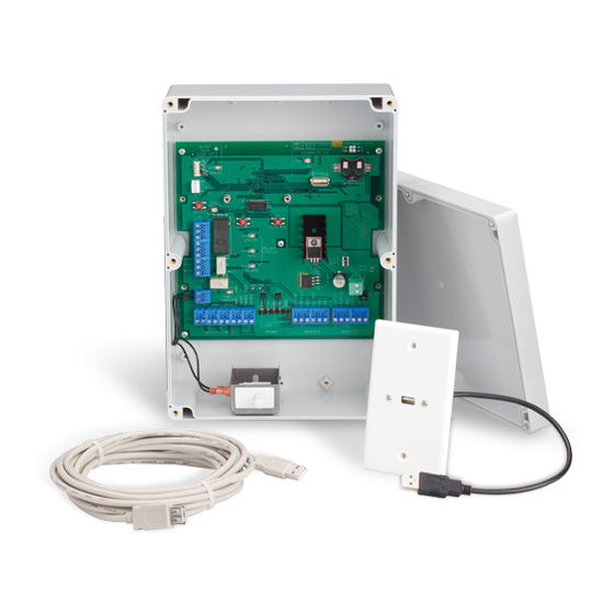
Offline controller user guide
Instructions for Adaptable Series offline controller
MOUNT
THIS
SIDE UP
J3
1
1
MCLR
TP21
VDD
LED1
TP22
GND
TP23
RB7
TP24
RB8
TP25
OPEN
IDAT
DEBUG
ICLK
1
RX
+3.3V
TX
GND
J1
S3
LED3
RX/TX
RESET
REL1
J6
1
STR
NO
STR
C
C
STR
NC
AUX
NO
AUX
C
AUX
NC
ALR_NO
ALR_C
ALR_NC
REL2
REL3
1
J2
LED7
GND
LID
PWR/
TAMPER
TAMPER
1
J13
SWITCH INPUT
CT5000
23394075_C
LED2
USB
1
J5
USB
S1
S2
LINK
SCHLAGE
LED4
STRIKE
RELAY
LED5
STATUS
AUX
U4
LED6
+5V
ALARM
LINE
LED8
LED9
U5
A-
B+
1
1
J11
J12
1
J10
1
J17
RS485
READER1
PRIMARY SIDE
BATTERY_HOLDER1
COIN CELL NOT NEEDED
IF RADIO BOARD PRESENT
+12V
J8
LINE
BATT
1
12/24VDC
1
J7
C32
J9
AA
1
BATT
1
J18
READER2
Advertisement
Table of Contents

Related Manuals for Schlage CT5000


Summary of Contents for Schlage CT5000
- Page 1 *P516-104* P516-104 CT5000 Offline controller user guide Instructions for Adaptable Series offline controller PRIMARY SIDE MOUNT THIS 23394075_C SIDE UP LED2 MCLR TP21 LED1 TP22 TP23 TP24 TP25 OPEN IDAT DEBUG ICLK BATTERY_HOLDER1 +3.3V COIN CELL NOT NEEDED IF RADIO BOARD PRESENT...
-
Page 2: Table Of Contents
Overview ...........................3 Getting started ........................4 Typical installation ......................4 Mount the CT5000 ......................5 CT5000 wiring connections ....................5 Wiring the CT5000 to access control peripherals ............5 CT5000 cable / wire specifications .................6 Switch inputs .........................7 Relay outputs ........................8 Relay output suppression diagram................8 Credential readers......................9... -
Page 3: Overview
Externally powered using a UL 294 power supply for UL installations and a ULC S318/ ULC S319 listed Class 2 power supply for cUL installations (not included) capable of sourcing at least 500 mA @ 12 or 24 VDC (example: Schlage models PS902, PS904, PS906). -
Page 4: Getting Started
CT5000 and the readers. (The CT5000 requires a power supply capable of sourcing at least 500 mA @ 12 or 24 VDC.) If preferred, separate UL294 or ULC S318/ULC S319 listed power sources for the CT5000 and the readers is an acceptable alternative. -
Page 5: Mount The Ct5000
CT5000 wiring connections Wiring the CT5000 to access control peripherals The CT5000 will interface with two (2) UL listed credential readers and supports three (3) output relays – strike, auxiliary and alarm and four (4) optional inputs – reader 1 tamper, reader 2 tamper, request to exit and door position switch. -
Page 6: Ct5000 Cable / Wire Specifications
J10 RS-485 connection is reserved for future expansion. Tamper input SW1 lid tamper switch monitors the state of the CT5000 enclosure lid and generates a tamper trouble signal when the lid is open. When terminals J2-1 and J2-2 are shorted, a tamper audit is recorded. -
Page 7: Switch Inputs
OR a signal level input for 5V logic. Any voltage greater than 5V may cause damage to either the CT5000 or the reader(s). Connect the shield of the electrified locking hardware input cables to the appropriate CT5000 GND terminal. -
Page 8: Relay Outputs
CT5000 signal wiring. Do not run relay output wires in the same cable or conduit as any other CT5000 wiring. Connect the shield of the relay output cables to the appropriate earth ground terminal of the electrified lock/load or auxiliary load power supply. -
Page 9: Credential Readers
XceedID models PR10, SM10, MT11, MT11-485, MT15, MT15-485, MTK15 and MTK15-485. Connect the shield of the reader 1 cable to the CT5000 J17-3 terminal (GND). Connect the shield of the reader 2 cable to the CT5000 J18-3 terminal (GND). Do not connect the cable shield at the credential reader. -
Page 10: Wiring Diagram Ct5000 X Magnetic Lock
UL or ULC Listed 12 or 24 VDC RTX Device (if required) To + 12 or 24 VDC of Card Reader* *IMPORTANT: Match Voltage of Power Supply to Card Reader Wiring diagram CT5000 x magnetic lock 10 • Schlage • CT5000 user guide... -
Page 11: Wiring Diagram Ct5000 X Electric Strike
UL or ULC Listed 12 or 24 VDC RTX Device (if required) To + 12 or 24 VDC of Card Reader* *IMPORTANT: Match Voltage of Power Supply to Card Reader Wiring diagram CT5000 x electric strike 11 • Schlage • CT5000 user guide... -
Page 12: Wiring Diagram Ct5000 X Dry Contact Relay
Wiring diagram CT5000 x dry contact relay Power failure modes The CT5000 strike relay can be configured to fail safe (fail unlocked) or fail secure (fail locked) using SUS on the HHD. The default state of the strike relay is fail secure or “normally closed (secure)”... -
Page 13: Remote Usb Connection
CT5000. DO NOT connect the USB cable to the CT5000 USB port (J5) yet. 2. Route the 15 foot USB cable from the CT5000 to where a U.S. single gang electrical box (not included) will be installed. Install the single gang box at this location. -
Page 14: Handheld Device (Hhd)
To connect the HHD to the CT5000: If a remote USB connection is being used, begin at step 3. 1. Loosen the 6 screws and remove the CT5000 lid. The POWER LED should blink green when the lid is off. -
Page 15: Construction Access Mode
3. When the POWER/TAMPER LED turns off, release the buttons. 4. After a 15 second delay, the CT5000 DEBUG LED and the reader’s LED will blink green for one second, and the reader will beep for one second. 5. Replace the lid. -
Page 16: Ct5000 Manual Programming
CT5000 manual programming Manual programming applies only to a CT5000 TIPS installed with a keypad credential reader. The default programming Keypad credential readers with ASCII with leading parity, code is 97531 and “*”. 4-bit and 8-bit formats allow manual programming. -
Page 17: Programming Legend
New [PIN] between each New Card step. add another credential OR to finish 1 Other lights may show before the final confirmation. Wait for the final confirmation before continuing to the next step. 17 • Schlage • CT5000 user guide... - Page 18 Delete Credential stop blinking Credential [PIN] between each delete another to finish step. credential 1 Other lights may show before the final confirmation. Wait for the final confirmation before continuing to the next step. 18 • Schlage • CT5000 user guide...
- Page 19 Press , OR for desired PIN length step. to finish 1 Other lights may show before the final confirmation. Wait for the final confirmation before continuing to the next step. 19 • Schlage • CT5000 user guide...
-
Page 20: Manual Programming Error Codes
Error codes are indicated at the reader by a blinking red LED. The number of red blinks indicates the error code. The CT5000 may not provide complete control of the reader’s beeper or LEDs. Please consult the reader’s manufacturer for instruction on reader configuration. -
Page 21: Ct5000 Coin Cell Battery
When installing the CT5000, after power is applied, remove the mylar strip from the coin cell battery. When the coin cell battery is low, the CT5000 will provide a delay after acceptance of a valid credential, and the POWER/TAMPER LED (LED7) will blink rapidly. The reader’s LED will indicate low battery with one green blink and three red blinks before allowing access. -
Page 22: Troubleshooting
• AUX relay action is assigned by the door programming. A credential must have AUX relay rights before the CT5000 will activate the AUX relay. The AUX relay will activate only when the CT5000 is in normal operating mode. •... -
Page 23: Ct5000 Led Reference
CT5000 LED reference 23 • Schlage • CT5000 user guide... -
Page 24: Fcc/Ic Statements
FCC/IC statements Allegion Agency statements Compliance Statement This device complies with Part 15 of the FCC Rules. Operation is subject to the following two conditions: This device may not cause harmful interference, and This device must accept any interference received, including interference that may cause undesired operation. Warning Changes or modifications not expressly approved by the party responsible for compliance could void the user’s authority to operate the equipment.
Need help?
Do you have a question about the CT5000 and is the answer not in the manual?
Questions and answers