Advertisement
Quick Links
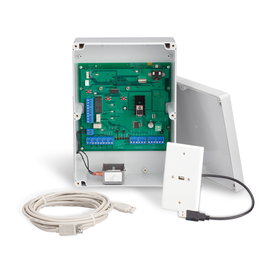
CT5000 USB Extender Kit
23865827
125-Foot USB Cable Extender
The 125-Foot USB Extender Kit is used to remotely program and configure the CT5000 up to 125 cable feet away from the CT5000.
The 125-Foot USB Extender Kit consists of:
(1) USB Extender Pair (includes 1 local and 1 remote unit)
(1) 125-Foot CAT5 Cable
(2) 3M™ Dual Lock™ Reclosable Fastener Pads
Additional equipment needed:
(1) U.S. Single Gang Electrical Box (minimum depth 3Z\x")
(1) Panel Mount USB Cable*
(1) USB Wall Plate*
* Included in the CT5000 package
1
Route the 125-Foot CAT5 Cable from the CT5000
to where a U.S. single gang electrical box
(not included) will be installed.
Install the U.S. single gang electrical box at
this location.
Avoid routing the cable near fluorescent light
ballasts, power transformers, etc. where electrical
interference may be present.
Avoid sharp twists or bends in the cable.
2
Remove the Panel Mount USB Cable and the USB
Wall Plate from the CT5000 package.
Connect the Panel Mount USB cable to the USB Wall
Plate using the included hardware as shown.
Panel Mount
USB Wall Plate
USB Cable
Installation Instructions
USB Extender
Local
Dual Lock
USB Extender
Fastener Pads
Remote
125-Foot CAT5 Cable
3
Connect the USB Extender Remote unit to the
Panel Mount USB Cable.
USB Extender
Remote unit
4
Route the 125-Foot CAT5 Cable through the single
gang electrical box and connect the cable to the
USB Extender Remote unit.
Avoid sharp twists or bends in the cable.
125-Foot CAT5 Cable
USB Extender
Remote unit
Electrical box must
be at least 3¹⁄₂" deep
5
Attach the USB Wall Plate to the single gang
electrical box using the included hardware.
Make sure the USB and CAT5 connections are
fully seated and cables are not pinched.
Tuck wire inside
the electrical box
6
Attach one Dual Lock pad to the inside of the
CT5000 enclosure as shown.
Attach the other Dual Lock pad to the USB
Extender Local unit as shown.
USB Extender
Local unit
7
Plug the USB Extender Local unit into the J5 USB
connector on the CT5000.
Attach the USB Extender Local unit to the Dual
Lock pad inside the CT5000 enclosure.
1¹⁄₂ - 2"
Dual Lock
Fastener Pad
USB Extender
Local unit
PRIMARY SIDE
MOUNT
THIS
23394075_C
SIDE UP
J3
1
1
MCLR
LED2
TP21
VDD
TP22
LED1
GND
TP23
RB7
USB
J5 USB
TP24
RB8
TP25
OPEN
IDAT
DEBUG
1
ICLK
J5
1
RX
BATTERY_HOLDER1
+3.3V
USB
TX
COIN CELL NOT NEEDED
GND
IF RADIO BOARD PRESENT
J1
S3
LED3
RX/TX
RESET
REL1
S2
S1
J6
1
STR
NO
STR
LINK
SCHLAGE
C
C
STR
NC
LED4
AUX
+12V
STRIKE
NO
AUX
C
RELAY
Customer Service Servicio al cliente Service à la clientèle
AUX
LED5
STATUS
NC
J8
AUX
LINE
ALR_NO
U4
ALR_C
LED6
BATT
+5V
1
12/24VDC
ALR_NC
REL2
ALARM
LINE
1-877-677-7011
www.allegion.com/us
1
REL3
LED8
LED9
J2
1
J7
LED7
C32
GND
U5
J9
A-
B+
1
1
LID
AA
PWR/
J11
J12
1
TAMPER
BATT
TAMPER
8
Route the 125-foot CAT5 cable through the hole in
the CT5000 enclosure. (See CT5000 Wiring
Connections in the CT5000 User Guide for details.)
Connect the 125-foot CAT5 cable to the USB
Extender Local unit.
PRIMARY SIDE
MOUNT
THIS
23394075_C
SIDE UP
J3
1
1
LED2
TP21
MCLR
VDD
TP22
GND
LED1
TP23
USB
RB7
TP24
RB8
TP25
OPEN
1
IDAT
DEBUG
ICLK
J5
1
RX
+3.3V
BATTERY_HOLDER1
USB
TX
COIN CELL NOT NEEDED
GND
IF RADIO BOARD PRESENT
J1
S3
LED3
RX/TX
RESET
REL1
J6
1
S2
S1
STR
NO
LINK
SCHLAGE
STR
C
C
STR
NC
LED4
+12V
AUX
STRIKE
NO
AUX
C
RELAY
AUX
LED5
STATUS
NC
J8
AUX
ALR_NO
LINE
U4
BATT
ALR_C
LED6
+5V
1
12/24VDC
ALR_NC
ALARM
REL2
LINE
1
REL3
LED8
LED9
J2
1
J7
LED7
C32
U5
GND
A-
B+
J9
1
1
LID
AA
PWR/
J11
J12
1
TAMPER
BATT
TAMPER
1
J13
1
J10
1
J17
1
J18
RS485
READER1
READER2
SWITCH INPUT
9
Test the installation.
a) Power the CT5000.
b) Connect the Schlage Utility So ware (SUS).
c) The SUS will display "New Lock" or the lock name.
If the display does not function as mentioned above, check
all wire connections and routing, and make sure the CT5000
has appropriate power. (Refer to the CT5000 User Guide for
CT5000 power requirements.)
10
CT5000 settings can now be viewed on the SUS.
To configure and program the CT5000, it must be
coupled with the SUS. Refer to the CT5000 User
Guide for coupling instructions.
NOTE: The CT5000 lid must be removed in order to
access the "Schlage" and "LINK" buttons to couple
with the SUS.
© Allegion 2014
23865827 Rev. 03/14-b
Advertisement

Related Manuals for Schlage CT5000

Summary of Contents for Schlage CT5000
- Page 1 Extender Local unit. The 125-Foot USB Extender Kit is used to remotely program and configure the CT5000 up to 125 cable feet away from the CT5000. The 125-Foot USB Extender Kit consists of:...
- Page 2 1¹⁄₂ - 2 po (38 - 51 mm) CT5000 para conocer las instrucciones de vinculación. aseguradoras Placa de NOTA: Se debe retirar la tapa del CT5000 para acceder a los Extensión USB remota recerrable pared del USB botones “Schlage” y "LINK" y vincular el CT5000 con el SUS.
Need help?
Do you have a question about the CT5000 and is the answer not in the manual?
Questions and answers