Table of Contents
Advertisement
WARNING
If the information in these instructions is not followed exactly, a fire or explosion may
result, causing property damage or personal injury.
Do not store or use petrol or other flammable vapours and liquids in the vicinity of this or
–
any other appliance.
WHAT TO DO IF YOU SMELL GAS
–
Do not try to light any appliances.
Do not touch any electrical switch; do not use any phone in your building.
Immediately call the National Gas Emergency Helpline on (Freephone) 0800 111999 or your gas
supplier from a neighbour's phone. Follow the instructions received.
Installation and service must be performed by a Gas Safe registered installer, service agency
–
or the gas supplier.
Installation
Manual
Model
NPE-24AWE
NPE-24SWE
NPE-32AWE
NPE-32SWE
These appliances are for use with natural gas or LPG.
(An LPG conversion kit is included with the water
heater.)
Type: B23-B33-B53-C13-C33-C43-C53-C63-C83
Keep this manual near this water heater for future reference
whenever maintenance or service is required.
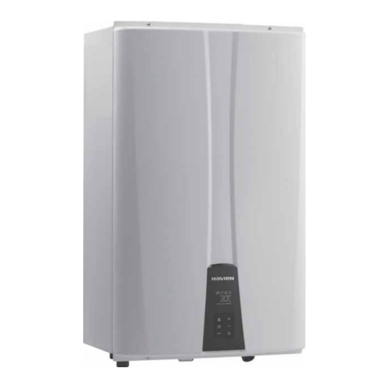
Condensing Water Heater
Advertisement
Table of Contents

Subscribe to Our Youtube Channel
Related Manuals for Navien NPE-32AWE


Summary of Contents for Navien NPE-32AWE
- Page 1 Condensing Water Heater Installation Manual Model NPE-24AWE NPE-24SWE NPE-32AWE NPE-32SWE These appliances are for use with natural gas or LPG. (An LPG conversion kit is included with the water heater.) Type: B23-B33-B53-C13-C33-C43-C53-C63-C83 Keep this manual near this water heater for future reference whenever maintenance or service is required.
-
Page 2: Table Of Contents
Contents 1. Safety Information 2. About the Water Heater 2.1 Items Included 2.2 Accessories 2.3 Specifications 2.4 The Front Panel 2.5 Components 2.6 Dimensions 3. Installing the Water Heater 3.1 Choosing an Installation Location 3.2 Mounting the Water Heater to the Wall 3.3 Connecting the Gas Supply 3.4 Connecting the Water Supply 3.5 Connecting the Condensate Drain Line... -
Page 3: Safety Information
1. Safety Information The following safety symbols are used in this manual. Read and follow all safety instructions in this manual precisely to avoid DANGER unsafe operating conditions, fire, explosion, property damage or personal injury. DANGER Indicates an imminently hazardous situation which, if not avoided, could result in severe injury or death. - Page 4 WARNING WARNING This appliance can be used by children aged from 8 years and above and persons with reduced physical, sensory or mental capabilities or lack of experience and knowledge if they have been given supervision or instruction concerning use of the appliance in a safe way and understand the hazards Do not store or use petrol or other involved.
- Page 5 Ministry of Industry and it must be started up by an Official Failure to do so may result in wiring Technical Assistance Service authorized by Navien. errors, which can lead to improper or All Gas Safe registered engineers carry an ID card with their dangerous operation.
- Page 6 CE marking and all relevant documentation. In the interest of customers, we are continuously endeavoring to make improvements in product Navien, hereby declares that the water heater models: quality. All the specifications stated in this document are therefore subject to change without notice.
-
Page 7: About The Water Heater
2. About the Water Heater 2.1 Items Included 2.2 Accessories When you open the box, you will find the following items with The following optional accessories are available for the water the water heater. Check the box for each of the following items heater: before installing the water heater. -
Page 8: Specifications
The following table lists the specifications for the water heater. Additional specifications about water, gas, electric, and air supplies (flue system) appear in the Installation section. Specifications Unit NPE-24AWE NPE-24SWE NPE-32AWE NPE-32SWE DHW input range 39.6 / 4.0 39.6 / 4.0 52.8 / 5.2 52.8 / 5.2... - Page 9 The following table lists the product information (EU regulation No 812/2013 and No 814/2013) KD Navien Symbol Unit NPE-24AWE NPE-24SWE NPE-32AWE NPE-32SWE Declared load profile Water heating energy efficiency class Water heating energy efficiency η 102.6 105.8 105.4 106.7 Daily electrical consumption 0.100...
-
Page 10: The Front Panel
2.4 The Front Panel The front panel allows you to adjust the water temperature and view the operating status or error codes. Remove the protective sheet from the front panel before using it. Error Master Unit A code will appear on the display Cascade operation Hot Water Recirculation Display... -
Page 11: Components
2.5 Components The following diagram shows the key components of the water heater. Component assembly diagrams and particular parts lists are included in the Appendixes. Coaxial Adapter Exhaust Limit Temperature Sensor Flue Duct Fan Motor Ignition Transformer Burner Dual Venturi Primary Heat Exchanger High Limit Switch Gas Pipe... - Page 12 Coaxial Adapter Exhaust Limit Temperature Sensor Flue Duct Fan Motor Ignition Transformer Burner Dual Venturi Primary Heat Exchanger High Limit Switch Gas Pipe Secondary Heat Exchanger APS (Air Pressure Sensor) Freeze Protection Switch Front Panel Condensate Trap PCB Box Gas Valve Flow Sensor Water Adjustment Valve Mixing Valve...
-
Page 13: Dimensions
2.6 Dimensions The following diagrams show the dimensions of the water heater and the table lists the supply connections. Supply Connections Description Diameter Ø60/100 Flue Exhaust / Air Intake Ø80/125 Hot Water Outlet 22 mm Recirculation Inlet 22 mm Cold Water Inlet 22 mm Gas Inlet 22 mm... - Page 14 Supply Connections Description Diameter Ø60/100 Flue Exhaust / Air Intake Ø80/125 Hot Water Outlet 22 mm Cold Water Inlet 22 mm Gas Inlet 22 mm Condensate Outlet 15 mm Overhead View Bottom View 38 mm 364 mm 115 mm 170 mm 60 mm 289 mm [NPE-24SWE/32SWE]...
-
Page 15: Installing The Water Heater
Installing the water heater in a location installation location: without a drain will void the warranty and Navien will not be responsible for water damage that occur as a result. For more information about condensate drainage, refer to Compliance Requirements “3.5 Connecting the Condensate Drain Line”... - Page 16 Adequate installation clearances Clearance from: Indoor Installation 250 mm minimum CAUTION Front 100 mm minimum Bottom 300 mm minimum Do not install the water heater on carpeting. Back 20 mm minimum Install the water heater in an area that allows for service and Sides 76 mm minimum maintenance access to utility connections, piping, filters,...
-
Page 17: Mounting The Water Heater To The Wall
WARNING The water heater is heavy. Always lift the unit with Navien NPE-AWE/NPE-SWE water heaters come with an upper assistance. Be careful not to drop the water heater while mounting bracket that is pre-drilled at 400 mm on centre for lifting or handling it to avoid bodily injury or damage to easy installation on standard wall studs. -
Page 18: Connecting The Gas Supply
3.3 Connecting the Gas Supply For the installation of any type of gas, the installer must be authorised by the Ministry of Industry and strictly follow the applicable Gas Regulations. The gas installation must comply with the Gas Installation Regulation. WARNING However, the following recommendations must be complied If a gas type other than the one specified on the water... - Page 19 3.3.1 Gas Pipe Material 3.3.3 Measuring the Inlet Gas Pressure WARNING WARNING The water heater must be left running for 10 minutes The water heater cannot function properly without before checking the gas pressure, to obtain thermal sufficient inlet gas pressure. Measuring the inlet gas equilibrium.
- Page 20 3. Leave the faucet on until the water heater shuts down due 5. Loosen the screws indicated in the figure below and to a lack of gas supply, and then turn off the hot water connect a manometer to the pressure port. Reset the faucet.
-
Page 21: Connecting The Water Supply
3.4 Connecting the Water Supply The following is a typical water piping example for NPE- 24AWE/32AWE models. When connecting the water supply, follow these guidelines: Do not remove the factory installed recirculation inlet cap unless a return line is connected to this fitting. Water leakage will occur if this cap is loose or missing ("A"... - Page 22 Internal Recirculation Mode model only) To use the internal recirculation mode: On all “AWE“ model Navien water heaters, you can choose from 1. Connect the water supply. two pre-heating modes: internal recirculation mode or external recirculation mode. To select a recirculation mode, you must set 2.
- Page 23 The following diagram shows the internal recirculation flow for 3. Set the front panel DIP switches at the far left (set of 10) to: pre-heating: 1—OFF; 2—ON. Primary Heat Exchanger Buffer Tank Secondary Heat Exchanger Flow Sensor 2-Way Circulation Check Valve Pump Valve...
- Page 24 3.4.2 External Pump Wire Connection 2. Locate the power switch on the right side of the front panel and switch the system off. An external pump may be connected to the water heater for recirculation applications. When selecting a circulator, it shall be sized to maintain a flow of 7 to 15 LPM through the water heater.
- Page 25 (see Recirculation Dipswitch Settings below). Condensate 9. Turn on the switch beside the front panel. Domestic Domestic Cold Water Hot Water Domestic Recirculation Return Recirculation Using Two Pumps (Navien Internal Pump & External Pump) Installing the Water Heater...
- Page 26 3.4.3 Connecting a Pressure Relief Valve When installing the valve, follow these guidelines: Ensure that the discharge capacity of the pressure relief valve is equal to or greater than the maximum pressure rating of the WARNING water heater. Ensure that the maximum kW rating on the pressure relief Improper installation of the pressure relief valve may valve is equal to or greater than the maximum input kW rating result in property damage or personal injury.
-
Page 27: Connecting The Condensate Drain Line
Before connecting the condensate drain, choose one of the following disposal options: Line The Navien NPE-AWE/NPE-SWE water heaters create condensation when it operates. This condensation has an acidic pH of 3-5. Follow all local codes and regulations when disposing of condensate from the water heater. We recommend draining the condensate into a laundry tub, as the alkali in laundry detergent will neutralize the acid in the condensate. -
Page 28: Flue System
To connect the condensate drain: 3.6 Flue System 1. Connect a drain line to the 13 mm fitting at the bottom of the water heater. WARNING Use only corrosion-resistant material for the drain line, such as PVC or CPVC. Do not reduce the size of this fitting or the Improper flue of the water heater can result in excessive drain line to less than 13 mm. - Page 29 The installation of the flue exhaust and combustion air Minimum Terminal Position intake system must be calculated and made by sufficiently Distance (mm) qualified and authorised staff. On designing and mounting the installation, all national and local regulations, standards and From openings (e.g.
- Page 30 3.6.2 Selecting a Flue System Dual Duct System For dual duct system, fit the components as shown in the figure: WARNING 1. Remove the air intake cap. The gas removal ducts must not be in contact with Air intake cap or near flammable materials and they must not pass through any structures or walls of buildings made of such materials.
- Page 31 3.6.3 Coaxial Systems 3.6.3.1 Horizontal Coaxial Removal (Type C Standard Removal System B 500 or 1,000 140 min W all Ø60/100 => Max. length: A+B-(2x45°elbow) = 20-2.4 = 17.6 m Ø60/100 => Max. length: A=20 m Ø80/125 => Max. length: A+B-(2x45°elbow) = 68-2.4 = 65.6 m Ø80/125 =>...
- Page 32 3.6.3.2 Vertical Coaxial Removal (Type C 3.6.4 Dual Duct Systems Standard Removal System 3.6.4.1 Horizontal Dual Duct Removal (Type C Standard Removal System Ø60/100 => Max. length: A=21 m Ø80/125 => Max. length: A=70 m Extended Removal System °elbow) Ø80/80 => Max. length: A+B+C-(1x90 = 110-2.2 = 107.8 m Minimum 350 mm Ø60/100 =>...
- Page 33 Extended Removal System 3.6.4.2 Vertical Dual Duct Removal (Type C Minimum 370 mm °elbow) Ø80/80 => Max. length: A+B+C+D+E+F-(4x90 = 110-(4x2.2) = 101.2 m Pipe Diameter Maximum Equivalent Elbow (mm) Length (m) Length (m) Ø80/80 90° °elbow) Ø80/80 => Max. length: A+B+C+D-(2x45 = 110-(2x1.4) = 107.2 m Pipe Diameter Maximum...
- Page 34 Carefully study the diagrams representing the different types of removal and select the one that best suits the conditions of your installation. To choose the removal accessories required for each installation, see the list of accessories on the NAVIEN price list. Maximum Total Length Pipe Diameter...
-
Page 35: Electrical Connections
3.7 Electrical Connections The water heater electrical connections must be made by sufficiently qualified staff in strict compliance with the sections below and with any electrical safety regulations applicable at WARNING the time of installation. The water heater has an electrical protection degree Note Improperly connecting the electrical supplies can result of IPX5D. -
Page 36: Setting The Dip Switches
3.8 Setting the DIP Switches The water heater has two DIP switch locations: on the main PCB and on the front panel. Each location has two sets of DIP switches that control the functionality of the water heater. Set the DIP switches appropriately, based on the installation environment. 3.8.1 PCB DIP Switches The two sets of DIP switches on the circuit board configure the water heater’s model settings. - Page 37 Dip Switch 1 (set of 10) Switch Function Setting Remark No Recirculation 1-OFF 2-OFF 3-OFF * Intelligent Preheating: Learns the user's hot water Recirculation Mode - c r i i t a N 2-OFF 3-OFF usage patterns and starts Internal Pump preheating prior to an c r i i t a...
-
Page 38: Installing A Cascading System
Gas Supply Line DHW Supply Line Cold Water Supply Line Recirculation Line [NPE-24AWE, NPE-32AWE] The recommended minimum recirculati is 7.57 LPM. Depending on the number of water Note heaters and the diameter of the recirculation line, it may not be necessary to connect all water heaters to the recirculation line. -
Page 39: Connecting The Communication Cables
When plumbing a cascading system, consider the following pipe diameters and flow rates. Note that flow rates above 2 m/s may Up to 16 water heaters can be connected with Navien Ready- cause pipe erosion. These specifications may vary depending on Link communication cables. - Page 40 2. On the slave water heater, press and hold the Diagnostic and Down appear on the display to confirm that this water heater is set as a slave. 3. Repeat step 2 to configure the rest of the slave water heaters in the system.
-
Page 41: Installation Checklist
After installing the water heater, review the following checklist. Complete the water heater start-up process by carrying out the checks listed in the table below. If you have additional questions or need assistance with installation, contact an official Technical Assistance Service (TAS) or refer to the technical support section of Navien’s website (www.navienuk.com). Check Value measured Notes Check that the water heater is filled with water and check for any leaks in the installation. -
Page 42: Maintaining The Water Heater
6. Maintaining the Water Heater 6.1 Cleaning the Water Heater 3. Close the gas valve. CAUTION Make sure the water heater is turned off and the power supply is disconnected before cleaning the water heater. The water heater may remain hot for several minutes after it is turned off. -
Page 43: Cleaning The Heat Exchanger
6. Remove the recirculation inlet filter from the bottom of the 6.3 Cleaning the Heat Exchanger water heater (“A” model only). WARNING Before cleaning the heat exchanger, make sure the water heater is off. To properly maintain the water heater, you should clean the heat exchanger annually. - Page 44 Remove 2 screws here to the heat exchanger and then remove the ignition transformer. NPE-24AWE/SWE and NPE-32AWE/SWE 7. Remove the screw connecting the fan motor assembly and the mixing chamber, and then remove the fan motor assembly. Maintaining the Water Heater...
-
Page 45: Cleaning The Inlet Water Filter And Recirculation Inlet Filter
It is important to keep electric parts of the water Note heater safe from water. Navien recommends to use a hose. If the water pressure of the hose is too high, water may splash to other electric parts of the water heater. -
Page 46: Protecting The Water Heater From Freezing
Freezing water heater. CAUTION 2. Close the gas valve. Damage due to freezing is not covered by the Navien limited warranty. If the water heater is connected to a circuit that could freeze, the circuit pipes must be suitably insulated. -
Page 47: Appendixes
7. Appendixes 7.1 Gas Conversion Included Items: ce Size (refer to below table) This water heater is c red for Natural Gas from the factory. If conversion to Propane Gas is required, the conversion kit Model supplied with the water heater must be used. NPE-24 AWE/SWE Ø4.80/Ø6.05 Ø3.85/Ø4.75... - Page 48 Procedure: 3. Once the front cover is removed, place it in a safe location to prevent accidental damage. With the internal components exposed, locate the gas inlet pipe and the Gas Valve near the 1. Turn off both gas and water supply to the water heater. left side of the unit which are highlighted in Figure 2.
- Page 49 DANGER damage. Navien water heaters are shipped ready to fire natural gas ONLY. See Figure 5. Inspect the O-ring and packing between the venturi, gas pipe and gas valve whenever they are disassembled.
- Page 50 8. Replace the gas inlet pipe to its original position and use all 11. Measure and adjust the gas/air ratio using a combustion screws to secure all connections. analyser (recommended). Perform the following tasks: a. Rotate and remove the cap to access the emissions Do not overtighten as this may damage or Note monitoring port as shown in Figure 7.
- Page 51 c. Fully open several hot water fixtures and set the 7.1.1 Setting the Operation Mode water heater to operate at 1-stage MIN mode (refer to 7.1.1Setting the Operation Mode). Measure the CO 1. Using the Front Panel, press and hold the Diagnostics Button value at low fire.
-
Page 52: Technical Data
7.2 Technical Data Pressure Drop Curve [NPE-24AWE/24SWE] [NPE-32AWE/32SWE] 52 Appendixes... - Page 53 Outlet Flow Data [NPE-24AWE] [NPE-32AWE] Appendixes...
- Page 54 38.0 34.1 30.3 26.5 22.7 19.0 15.4 11.4 -1.1 15.6 32.2 48.9 65.6 [NPE-24SWE] 49.2 45.4 41.6 38.0 34.1 30.3 26.5 22.7 19.0 15.4 11.4 -1.11 15.6 32.2 65.6 [NPE-32SWE] 54 Appendixes...
-
Page 55: Wiring Diagram
7.3 Wiring Diagram CON8 CON6 CON7 CON9 [NPE-24AWE/32AWE/24SWE/32SWE] Appendixes... -
Page 56: Ladder Diagram
7.4 Ladder Diagram LIVE NEUTRAL EXT_PUMP Relay 1 FILTER VENTURI Relay 2 Relay 3 IGNITER Relay 4 PUMP Primary Primary SMPS Speed Control DC15V Secondary DC24V DC12V Water Adjust 200V FSA Power Valve DC5V Switch Flow Control Flame Rod Flow Sensor H.T.L WD-PSS Hall Sensor... - Page 57 LIVE NEUTRAL EXT_PUMP Relay 1 FILTER VENTURI Relay 2 Relay 3 IGNITER Relay 4 PUMP Primary Primary SMPS Speed Control DC15V Secondary DC24V DC12V 200V FSA Power DC5V Switch Water Mixing Water Adjust Valve Valve Flame Rod Flow Sensor H.T.L WD-PSS Hall Sensor Outlet...
-
Page 58: Component Assembly Diagrams And Parts Lists
7.5 Component Assembly Diagrams and Parts Lists 7.5.1 Case Assembly Description Model Description Model Air Intake Cover Seal Case Bracket Case Coaxial Adapter Air Pressure Sensor Rubber Ring Panel Bracket Saddle NPE-24SWE/32SWE Cover Saddle Bracket 1 NPE-24SWE/32SWE Case Lower Bracket Freeze Protector Sensor NPE-24SWE/32SWE Freeze Protector Sensor Bracket... - Page 59 Fan O-Ring (G50) WPA-A (Screw) Fan Bracket(F) 11-1 Thermistor Flow Sensor Assembly Fastner Fan Bracket(R) Ignition Transformer NPE-24AWE Fastner Cold Inlet Pipe NPE-32AWE Ignitor O-Ring (Φ17.5x2.7t) Damper WPA-A (Clip) Buffer Tank Inlet Adapter Thermistor 17-1 O-Ring (P16) WPA-B Thermistor NPE-24AWE...
- Page 60 7.5.3 Burner Assembly(NPE-24SWE/32SWE) Description Model Description Model Ignition Transformer Fan Bracket (F) Fan Bracket (R ) Backup Ring Thermistor Exhaust High Limit Switch NPE-24SWE Fastner Heat Exchanger Assembly NPE-32SWE WPA-A (Clip) Ignitor Thermistor Water Packing (Φ26.5x2.4t) WPA-B NPE-24SWE NPE-24SWE/24AWE Heat Exchanger Outlet Pipe H-Ex Middle Pipe NPE-32SWE NPE-32SWE/32AWE...
- Page 61 7.5.4 Waterway Assembly(NPE-24AWE/32AWE) 12-5 12-4 12-2 12-3 12-1 Description Model Description Model Description Model Buffer Tank 4-2 Drain Plug 9-3 O-Ring (P16) Hot Water Outlet Pipe Assembly 4-3 O-RING (P18) Return Pipe clip 2-1 Pipe Adapter Fastner Fastner 2-2 O-RING (P20) Water Adjustment Valve Cold Water Inlet Pipe (WAV)
- Page 62 7.5.5 Waterway Assembly(NPE-24SWE/32SWE) Description Model Description Model Bracket Outlet Adapter Thermistor Fastner Water Filter Water Adjustment Valve (WAV) Cold Water Inlet Adapter Inlet Adapter O-Ring (P15) O-Ring (P18) Fastner How Water Outlet Adapter Flow Sensor Siphon O-Ring (P16) Siphon Hose Flow Sensor Outlet Adapter 62 Appendixes...
- Page 63 7.5.6 Fan(Gas) Assembly Description Model Description Model NPE-24AWE/24SWE NPE-24AWE/24SWE Gas Adapter Silence Adapter NPE-24AWE/24SWE O-Ring (P20) Gas Pipe NPE-32AWE/32SWE O-Ring (G75) Gas Valve NPE-24AWE/24SWE Gas Orifice Gas Inlet Adapter NPE-32AWE/32SWE i r u NPE-24AWE/24SWE O-Ring (P34) Dual Venturi NPE-32AWE/32SWE NPE-24AWE/24SWE...
- Page 65 SERVICE RECORD It is recommended that your heating system is serviced regularly and that the appropriate Service Interval Record is completed. Service Provider SERVICE 01 SERVICE 02 ² % ² % ² % ² % SERVICE 03 SERVICE 04 ² % ²...
- Page 66 Memo...
- Page 68 Model number Serial number Date purchased Installation location and type Error code, if any appears on the front panel display. Version: 1.02(Apr. 23, 2018) Navien Ltd 3000 Cathedral Hill, Guildford, Surrey, GU2 7YB TEL 0844 332 2323 www.navien.co.uk...
Need help?
Do you have a question about the NPE-32AWE and is the answer not in the manual?
Questions and answers