
Related Manuals for Acard AEC-7722

Summary of Contents for Acard AEC-7722
- Page 1 AEC-7722/AEC-7726H/Q ARS-2100/2100Q/ARS-2120 ARS-2000LFS/ARS-2000LHS LVD SCSI-to-IDE Bridges User’s Manual Version: 1.2 Copyright © 2006 ACARD Technology Corp. Release: October 2006...
- Page 2 ACARD and SCSIDE are the trademarks of ACARD Technology Corp. IBM is the trademark of International Business Machine Corporation. Microsoft and the Win- dows Logo are the registered trademarks, and Windows is the trademark of Microsoft Corporation.
- Page 3 Member nations already established their free of charge recycle systems of WEEE before August 13, 2005. Accordingly, ACARD has to be responsible for recycling all products exported to Germany. You can return your ACARD product that needs recycling to a local collector.
- Page 4 Los paises miembros ya han establecido su sistema de reciclaje gratuito de RAEE antes del 13 de Agosto del 2005. Por este motivo ACARD es el responsable del reciclaje de todos los productos exportados a Alemania. Usted puede devolver su producto ACARD a un punto de recogida local cuando desee reciclarlo.
-
Page 5: Table Of Contents
3.2.1 Supported DVD-ROMs ............. 18 3.2.2 Supported SCSI Adapters ............18 3.2.3 Supported Recording Software ..........18 3.2.4 Supported HDDs ................ 19 3.3 Installing AEC-7722........... 19 3.3.1 5.25” DVD-ROM ................ 19 3.3.2 Internal Power Connection ............20 3.3.3 Cable Connection ............... 20 3.4 Installing AEC-7726H/Q .......... - Page 6 3.8 Installing ARS-2000LHS ..........30 3.8.1 2.5” HDD ..................30 3.8.2 Internal Power Connection............31 3.8.3 Cable Connection............... 32 3.9 Jumper Setting on AEC-7722 ........33 3.10 Jumper Setting on AEC-7726H/Q ......34 3.11 Jumper Setting on ARS-2100/2100Q ......34 3.12 Jumper Setting on ARS-2120 ........35 3.13 Jumper Setting on AEC-2000LFS ......36...
-
Page 7: Chapter 1 About Scside
ROM interface can be used as the firmware upgrade of flash ROM. In ACARD’s technologies there is a perfect firmware design as well. It makes the transformation of IDE to SCSI really “plug and play”. The firmware has been tested on many kinds of IDE DMA66 /100/133 HDDs, CD-ROMs and DVD-ROMs. -
Page 8: Scside Design
LVD SCSIDE Bridge Manual enjoy the advantages of SCSI. With the intelligent firmware design, you don’t need ® to install a driver into the operating system so as to use SCSIDE products. In the operating system it is just a SCSI device. Figure 1-1 ®... -
Page 9: Chapter 2 Introduction
The programmable IDE access modes, including PIO mode 0, 1, 2, 3, 4 Multiword DMA mode 0, 1, 2 Ultra DMA mode 0~5 (transfer rate is 66MB/sec in AEC-7722 and 133MB/ sec in AEC-7726H/Q). The on-board flash ROM is easy to update firmware. -
Page 10: Details
2. ARS-2100/2100Q, ARS-2120, ARS-2000LFS and ARS-2000LHS have the following features: Easy to install. On-chip high speed ACARD RISC microcontroller. The transfer rate of LVD SCSI interface up to 160MB/sec. Supports ATA 66/100/133 HDD. The on-board flash ROM is easy to update firmware. -
Page 11: Specifications
LVD SCSIDE Bridge Manual 2.3.2 Specifications AEC-7722 Environment: 0° Temperature C to 50 ° C for operation −20° C to 85 ° C for storage Humidity 15% to 90% Dimension: L 12 W 3.5 cm 2.5 cmm AEC-7726H/Q Environment: 0°... - Page 12 LVD SCSIDE Bridge Manual Dimension 11.5 cm 7.1 cm ARS-2000LFS Environment: Temperature 0° C to 50 C for operation ° −20° C to 85 ° C for storage Humidity 15% to 90% Dimension: L 13.8 cm W 10.2 cm 1.3 cm ARS-2000LHS Environment: 0°...
-
Page 13: Outlines
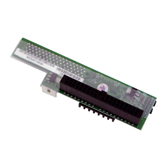
LVD SCSIDE Bridge Manual 2.3.3 Outlines 1. AEC-7722 CN1--- 68-pin female SCSI connector. CN2 --- 40-pin female IDE connector. CN3 --- 4-pin power connector. JP1 --- Refer to Figure 3-16 on page 33. JP2 --- Refer to Figure 3-17 on page 33. - Page 14 LVD SCSIDE Bridge Manual 2. AEC-7726H/Q CN1 --- 68-pin female SCSI connector. CN2 --- 40-pin female IDE connector. CN3 --- 4-pin power connector. JP1 --- Refer to Figure 3-18 on page 34. Figure 2-2a Figure 2-2b...
- Page 15 LVD SCSIDE Bridge Manual 3. ARS-2100/2100Q CN1 --- 68-pin female SCSI connector. CN2 --- 40-pin female IDE connector. CN3 --- 4-pin power connector. SW1 --- Refer to Figure 3-19 on page 34. LED1 (Green) --- for indicating power. LED2 (Red) --- for indicating operation. LED2 SW1 CN3 LED1 Figure 2-3...
- Page 16 LVD SCSIDE Bridge Manual 4. ARS-2120 CN1 --- 68-pin female SCSI connector. CN2 --- 40-pin female IDE connector (Slave). CN3 --- 40-pin female IDE connector (Master). CN4 --- 4-pin power connector. SW1 --- Refer to Figure 3-20 on page 35. SW2 --- Refer to Figure 3-21 on page 35.
- Page 17 LVD SCSIDE Bridge Manual 5. ARS-2000LFS CN1 --- 68-pin female SCSI connector. CN2 --- 40-pin female IDE connector. CN3 --- 4-pin power connector, for supplying power to HDD. CN4 --- 4-pin power connector, for supplying power to the bridge. JP1 --- Refer to Figure 3-22 on page 36. SW1 --- Refer to Figure 3-23 on page 36 CN3 SW1 Figure 2-5...
- Page 18 LVD SCSIDE Bridge Manual 6. ARS-2000LHS CN1 --- 68-pin female SCSI connector. CN5 --- 44-pin female IDE connector. CN4 --- 4-pin power connector, for supplying power to the bridge. JP1 --- Refer to Figure 3-24 on page 37. SW1 --- Refer to Figure 3-25 on page 37. Figure 2-6...
-
Page 19: Chapter 3 Hardware Installation
Chapter 3 Hardware Installation Hardware installation includes two parts. The first part is the installation of SCSI adapter like AEC-67160. The second part is the installation of AEC-7722 or AEC- 7726H/Q, etc. Yet, you have to set jumpers at first (see page 33-37). -
Page 20: Compatibility
MATSUSHITA 3.2.2 Supported SCSI Adapters Through AEC-7722 an IDE DVD drive can be transformed into a SCSI one, but most CD recording software still regards it as an IDE one . Thus the recording soft- ware will send 12-byte IDE commands. Only a special SCSI adapter such as AEC- 67160 can solve the problem. -
Page 21: Supported Hdds
3.5” HDD IBM HDD MAXTOR HDD SEAGATE HDD WESTERN DIGITAL HDD 2.5” HDD IBM HDD Fujitsu HDD 3.3 Installing AEC-7722 3.3.1 5.25” DVD-ROM AEC-7722 is designed to meet 5.25” DVD-ROMs or DVD writers. Extra accesso- ries are not needed in installaiton. -
Page 22: Internal Power Connection
Figure 3-2 3.3.3 Cable Connection Before connecting AEC-7722 to a DVD drive, you should tell the SCSI connector from the IDE one. On the bridge the 68-pin connector is for SCSI adapter while the 40-pin one for IDE device. There is a new SCSI cable in the package of SCSI adapter... - Page 23 LVD SCSIDE Bridge Manual 1. Find out pin 1 of CN2 on AEC-7722. 2. Find out pin 1 of the connector on the IDE DVD drive. 3. Parallel these two connectors by pin 1 to pin 1 and connect them.
-
Page 24: Installing Aec-7726H/Q
LVD SCSIDE Bridge Manual 3.4 Installing AEC-7726H/Q 3.4.1 3.5” HDD AEC-7726H/Q is designed for ATA hard drive. Extra accessories aren’t needed. 3.4.2 Internal Power Connection There are two kinds of internal power connectors providing power to the IDE device and AEC-7726H/Q circuit board separately. The large connector of the Y-splitter power cord is for most IDE devices while the small one for AEC-7726H/Q. -
Page 25: Cable Connection
LVD SCSIDE Bridge Manual 3.4.3 Cable Connection Before connecting AEC-7726H/Q to a hard drive, you should tell the SCSI connector from the IDE one. On the bridge the 68-pin connector is for SCSI adapter while the 40-pin one for IDE device. There is a new SCSI cable in the package of SCSI adapter (optional). -
Page 26: Installing Ars-2100/2100Q
LVD SCSIDE Bridge Manual 3.5 Installing ARS-2100/2100Q 3.5.1 3.5” HDD ARS-2100/2100Q is designed to meet 3.5”HDDs. Extra accessories aren’t needed. 3.5.2 Internal Power Connection The large connector of the Y-splitter power cord is for most IDE devices while the small one for ARS-2100/2100Q. Figure 3-6... -
Page 27: Cable Connection
LVD SCSIDE Bridge Manual 3.5.3 Cable Connection Before connecting ARS-2100/2100Q to a hard drive, you should tell the SCSI connector from the IDE one. On the bridge the 68-pin connector is for SCSI adapter while the 40-pin one for IDE device. There is a new SCSI cable in the package of SCSI adapter (optional). -
Page 28: Installing Ars-2120
LVD SCSIDE Bridge Manual 3.6 Installing ARS-2120 3.6.1 3.5” HDD ARS-2120 is designed to connect two 3.5”HDDs. Extra accessories aren’t needed. 3.6.2 Internal Power Connection The large connector of the Y-splitter power cord is for most IDE devices while the small one for ARS-2120. -
Page 29: Cable Connection
LVD SCSIDE Bridge Manual 3.6.3 Cable Connection Before connecting ARS-2120 to 2 hard drives, you should tell the SCSI connector from the IDE one. On the bridge the 68-pin connector is for SCSI adapter while the 40-pin one for IDE device. There is a new SCSI cable in the package of SCSI adapter (optional). -
Page 30: Installing Ars-2000Lfs
LVD SCSIDE Bridge Manual 3.7 Installing ARS-2000LFS 3.7.1 3.5” HDD ARS-2000LFS is designed to meet 3.5”HDDs. Put the hard drive on the bridge and connect it to the 40-pin CN2 (see Figure 2-5 on page 15). Then screw it from the bottom with 4 golden screws as the following picture shows. -
Page 31: Cable Connection
LVD SCSIDE Bridge Manual Figure 3-11 3.7.3 Cable Connection Before connecting ARS-2000LFS to a hard drive, you should tell the SCSI connector from the IDE one. On the bridge the 68-pin connector is for SCSI adapter while the 40-pin one for IDE device. There is a new SCSI cable in the package of SCSI adapter (optional). -
Page 32: Installing Ars-2000Lhs
LVD SCSIDE Bridge Manual 5. Find out pin 1 of CN1 on ARS-2000LFS. 6. Find out the colored pin 1 of the connector on the other end of SCSI cable, and connect to CN1 of ARS-2000LFS. Figure 3-12 3.8 Installing ARS-2000LHS 3.8.1 2.5”... -
Page 33: Internal Power Connection
LVD SCSIDE Bridge Manual Figure 3-13 3.8.2 Internal Power Connection On ARS-2000LHS because the 44-pin CN5 supplies power to the hard drive, there is no need of a small 4-pin connector. As to CN4, the large 4-pin connector, it sup- plies power to the bridge. -
Page 34: Cable Connection
LVD SCSIDE Bridge Manual 3.8.3 Cable Connection Before connecting ARS-2000LHS to a hard drive, you should tell the SCSI connector from the IDE one. On the bridge the 68-pin connector is for SCSI adapter while the 44-pin one for IDE device. There is a new SCSI cable in the package of SCSI adapter (optional). -
Page 35: Jumper Setting On Aec-7722
3.9 Jumper Setting on AEC-7722 There are two jumpers on AEC-7722: JP1 and JP2. JP1 has 6 pins in 3 columns. Column 1 and 2 are for reserve, and column 3 is for single end (SE). JP2 has 14 pins in 7 columns. -
Page 36: Jumper Setting On Aec-7726H/Q
LVD SCSIDE Bridge Manual 3.10 Jumper Setting on AEC-7726H/Q There is only one jumper on AEC-7726H/Q. JP1 has 14 pins in 7 columns. Column 1 is for ID1, column 2 for ID2, column 3 for ID4, column 4 for ID8, column 5 for RSV0, column 6 for RSV1 and column 7 for LED. -
Page 37: Jumper Setting On Ars-2120
LVD SCSIDE Bridge Manual 3.12 Jumper Setting on ARS-2120 SW1 is mainly used to set each device’s ID number on the SCSI adatper. Give your IDE device a specific number according to the following figure. 1 for ID1 2 for ID2 3 for ID4 4 for ID8 Figure 3-20... -
Page 38: Jumper Setting On Aec-2000Lfs
LVD SCSIDE Bridge Manual 3.13 Jumper Setting on ARS-2000LFS There is one jumper on ARS-2000LFS. JP1 has 10 pins in 5 columns. Column 1 is for ID1, column 2 for ID2, column 3 for ID4, column 4 for ID8, and column 5 for delay start (to control the drive’s spin-up). -
Page 39: Jumper Setting On Ars-2000Lhs
LVD SCSIDE Bridge Manual 3.14 Jumper Setting on ARS-2000LHS There is one jumper on ARS-2000LHS. JP1 has 10 pins in 5 columns. Column 1 is for ID1, column 2 for ID2, column 3 for ID4, column 4 for ID8, and column 5 for reserve. -
Page 40: Chapter 4 Troubleshooting
LVD SCSIDE Bridge Manual Chapter 4 Troubleshooting 4.1 Basic Troubleshooting After installing AEC-7722, AEC-7726H/Q, ARS-2100/ARS-2100Q, ARS-2120, ARS-2000LFS or ARS-2000LHS, if it cannot work, check the following things. 1. Check SCSI host adapter Check if the adapter is firmly inserted into PCI slot on the motherboard. -
Page 41: Advanced Troubleshooting Of 7722
LVD SCSIDE Bridge Manual 4.2 Advanced Troubleshooting of 7722 Here we connect AEC-7722 to RICOH MP5120A, a DVD drive, to explain the troubleshooting in operating system. At first, set the SCSI ID number on AEC-7722 as 0, and then inspect in Windows XP. - Page 42 LVD SCSIDE Bridge Manual Step 2. Double click “Control Panel”. Figure 4-2 Step 3. Double click “Printers and Other Hardware”. Then, double click “System” on the left. After entering “System Properties”, click “Hardware”, “Device Man- ager”. Then, double click “SCSI and RAID controllers” to check if AEC-67160 adapter is installed well.
- Page 43 If you can find the IDE device connected to AEC-7722 in “Device Manager”, AEC- 7722 has been installed successfully. If you cannot find, but see a yellow question mark, check the IDE connector on AEC-7722. It could be a bad connection or the device’s malfunction. Check your IDE device as follows.
-
Page 44: Advanced Troubleshooting Of 7726H/Q
LVD SCSIDE Bridge Manual Step 2. Double click to enter “General”, and see if the device is working normally. Besides, you can see if the target ID is correct. Figure 4-5 4.3 Advanced Troubleshooting of 7726H/Q Here we connect AEC-7726H/Q to Maxtor 6L040J2, a hard drive, to explain the troubleshooting in operating system. - Page 45 LVD SCSIDE Bridge Manual 1. Check SCSI host adapter Check if the displayed device on the list of devices is just the installed SCSI adapter. The steps of entering “Device Manager” are as follows. Step1. Double click “My Computer”. Figure 4-6 Step 2.
- Page 46 LVD SCSIDE Bridge Manual Step 3. Double click “Printers and Other Hardware”. Then, double click “System” on the left. After entering “System Properties”, click “Hardware”, “Device Man- ager”. Then, double click “SCSI and RAID controllers” to check if AEC-67160 adapter is installed well. Figure 4-8 2.
- Page 47 LVD SCSIDE Bridge Manual Step 1. Click “Disk drives” to show your HDD in “Device Manager”. Figure 4-9...
- Page 48 LVD SCSIDE Bridge Manual Step 2. Double click to enter “General”, and see if the device is working normally. Besides, you can see if the target ID is correct. Figure 4-10...
- Page 49 Technical Support Form Email: support@acard.com http://www.acard.com Model F/W Version Hard Disk Model/type Capacity Firmware version Others Problem Description...
Need help?
Do you have a question about the AEC-7722 and is the answer not in the manual?
Questions and answers