Table of Contents
Advertisement
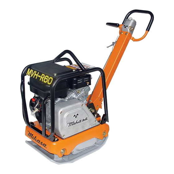
REVERSIBLE COMPACTOR
INSTRUCTION MANUAL
Contents of Declaration of Conformity
We thank you for selecting Mikasa
Vibration Compactor. For your safe
and proper operation, please read
this manual and be always sure to
keep it ready for reference.
Please refer the
EC DECLARATION OF CONFORMITY
Original
in this manual as well.
402-04504
Advertisement
Table of Contents

Related Manuals for Mikasa MVH-R60


Summary of Contents for Mikasa MVH-R60
- Page 1 REVERSIBLE COMPACTOR INSTRUCTION MANUAL Contents of Declaration of Conformity We thank you for selecting Mikasa Vibration Compactor. For your safe and proper operation, please read this manual and be always sure to keep it ready for reference. Please refer the...
- Page 3 2) Manufacturer’s name and address. 4-3, Sarugaku-cho 1 chome, Chiyoda-ku, Tokyo101-0064, Japan Yoshiharu Nishimaki, engineer 3) Name and address of the person who keeps the R. & D. Division, Mikasa Sangyo Co., Ltd. technical documentation. Shiraoka-machi, Saitama, Japan 4) Type: Vibratory Plates...
-
Page 4: Table Of Contents
TABLE OF CONTENTS 1. Preface ..................1 2. Applications, Warnings, Power Transmission of Machine ..1 3. Warning Symbols ..............3 4. Safety Precautions ..............3 General Precautions ............ 3 Refueling Precautions ..........4 Location and Ventilation Precautions ......4 Precautions Before Starting ........ -
Page 5: Preface
For inquiries about repair parts, parts lists, service manuals, and repairs, please contact the store where you purchased the product, our sales office, or the Mikasa Parts Service Center. For parts lists, please visit our homepage at: http://www.mikasas.com/ where you can access Mikasa WEB parts lists. - Page 6 Through this process, the engine revolution is changed to the pendulum revolution suitable for compacting. The vibrator pulley rotates the pendulum axis of the drive side. The two pendulums inside the vibrator are fixed to the two pendulum axes that are positioned in parallel and are connected with the gear.
-
Page 7: Warning Symbols
Before inspection and maintenance work, stop the engine, and do your work on a flat surface area. If a cell is attached, remove the battery wiring before your work. ■ Mikasa does not accept any responsibility for accidents caused by remodeling or rework done on the machine. -
Page 8: Refueling Precautions
4-2. Refueling Precautions DANGER ! ■ When adding fuel, Make sure you work in a well ventilated location. Make sure the engine is stopped and wait until it cools down. Take the machine to a clear flat loca- tion without any combustibles nearby. Be careful not to spill the fuel. -
Page 9: Transportation And Storage Precautions
Lifting Precautions (Continued) ■ Stop the engine and shut the fuel cock while lifting. ■ Use a sufficiently strong wire rope. ■ For lifting, use only one point hoisting hook, and do not lift at any other part. ■ When the machine is hoisted, never let people or animals come under- neath. -
Page 10: Labeling Positions
4-9. Labeling Positions MVH-R60 -120 -150 Label No. Parts No. Parts Name Remarks PLATE, SERIAL NO. 9201-10000 DECAL, MODEL/MVH-R60 MVH-R60 9202-07440 DECAL, MODEL/MVH-120 MVH-120 9202-07660 DECAL, MODEL/MVH-150 MVH-150 9202-09620 DECAL, CAUTION/R60 MVH-R60 9202-07400 DECAL, DANGER-CAUTION/MVH-150 MVH-120/150 9202-07420 DECAL, V-BELT RPF-3320... -
Page 11: Description Of Symbols Used On Warning Labels
4-10. Descriptions of Symbols Used on Warning Labels Label No.3 Pars No.9202-07400 (MVH-120/150) Label No.3 Pars No.9202-09620 (MVH-R60) DANGER DANGER DANGER DANGER ① ③ ② ※Engine type except L48 FUEL EXHAUST LIFTING LIFTING ① ③ ④ ② Operate only in well-... - Page 12 Fire hazard Stop the engine when refueling. Fire may occur if a flame is near the tank fuel port. Danger: poisonous exhaust gas Carbon monoxide poisoning may occur if the exhaust gas is inhaled. Do not operate the machine in a poorly ventilated area. Do not go under the lifted machine.
-
Page 13: Specifications
5. Specifications MVH-150D MVH-120GH Model MVH-R60 MVH-120GR MVH-150GH MVH-150GR MVH-150D [VAS] (Silent Type) Dimensions(mm) Overall Length 1030 [1120] 1030 1130 1130 1130 1130 Overall Width Overall Height 900 [990] Plate Size 350 x 480 400 x 585 400 x 585... -
Page 14: Appearance
6. Appearance 6-1. Outside Dimension (mm) MVH-R60 MVH-R60 MVH-120 MVH-150 400 (MVH-120) 585 (MVH-120) 700 (MVH-150) 430 (MVH-150) 1030 (MVH-120) 1120 (MVH-120 VAS) 1130 (MVH-150) -
Page 15: Parts And Component
6-2. Parts and Component BREATHER CAP TRAVEL LEVER HAND PUMP REVERSE Hydraulic oil : Shell Terrace Oil #46 or equivalent NEUTRAL FORWARD THROTTLE LEVER LIFTING FOOK HANDLE (STORING GUARD FRAME POSITION) HANDLE ENGINE (WORKING POSITION) BELT COVER VIBRATION CASE HANDLE GRIP THROTTLE LEVER STARTING KNOB HANDLE LOCK... -
Page 16: Inspection Before Operation
Check the oil gauge to see if the oil is at the specified level. Use engine oil SAE10W-30 as lubrication oil. Recommended oil quantity for MVH-R60 is 200cc and MVH-120/150, 350cc. (Fig. 2) Effective... -
Page 17: Operation
8. Operation 8-1. Starting Gasoline Engine Set the fuel cock lever to the “Out” position to let the fuel flow. (Fig. 3-1, 3-2, 3-3) Fuel Cock (HONDA) Fuel Cock (ROBIN EX-TYPE) “ O ” Fuel Cock Lever “ l ” FLOW Fuel Cock Lever fig.3-2... - Page 18 Slightly move the throttle lever at the handle to Throttle Lever high. (Fig. 5) fig.5 Turn the engine switch to “ON (operation)”. (Fig.6) Engine Switch HONDA ROBIN “ON” “ON” fig.6 Hold the recoil starter grip, and pull it a little. You will feel a slight resistance.
- Page 19 Choke (ROBIN EH-TYPE) Choke (ROBIN EX-TYPE) Choke Lever Operation(Open) Operation(Open) Choke Lever fig.8-3 fig.8-2 After the engine has started, warm up the engine at low speed for 2 to 3 minutes. This is especially important in cold weather. While warming up, check for any abnormalities suchas gas leakage.
-
Page 20: Diesel Engine
Diesel Engine (MVH-150D) Open the fuel cock lever. (Fig 9) Fuel Cock Close Open fig.9 Open the throttle lever to about 30° for the Throttle Lever idling position. (Fig.10) Open by about 30 degress fig.10 Recoil starter Recoil Starter CAUTION !... -
Page 21: Operation
8-2. Operation CAUTION ! While the machine is in operation, make sure there is no object or structure that might cause injury or machine damage in the direction that the machine is moving. If the throttle lever is opened suddenly, the machine starts to operate. -
Page 22: Stopping The Machine
9. Stopping the Machine Move the throttle lever from ON to OFF (for diesel engine, to idle position). Run the engine for 3 to 5 minutes at low speeds to cool it down before stopping. Diesel Engine Move the throttle lever to the stop position to stop the engine. -
Page 23: Transportation
10. Transportation WARNING ! ■ Make sure there is no breakage of guard frame and anti-vibration rubber nor loosened or missing bolts. ■ Always stop the engine when lifting. ■ Use an intact wire rope without any deformation with sufficient strength. ■... -
Page 24: Regular Check And Adjustment
12. Regular Check and Adjustment 12-1. Inspection and Maintenance Schedule Table Check parts Check items Oils Check frequency Appearance Flaw, deformation Fuel tank Leakage gasoline Fuel system Leakage Engine oil Leakage, oil level, dirt Engine oil Shock absorber Crack, damage, wear Hand pump Leakage Hydraulic oil... -
Page 25: Changing The Engine Oil
12-2. Changing the Engine Oil Perform the first engine oil change after 20 hours of operation, then change at every 100 hours. 12-3. Cleaning the Air Cleaner When the air cleaner element becomes dirty, the engine does not start smoothly, and suffi- cient output cannot be obtained. -
Page 26: Checking/Changing The Vibrator Oil
Not necessary to screw the machine. ※ Use engine oil SAE 10W-3D as lubrication fig.18 oil. The quantity used is 200cc for MVH-R60 and 350cc for MVH-120/150. CAUTION ! When checking the vibrator oil, clean the oil port beforehand to prevent dust and other foreign materials from falling into the oil. - Page 27 Pour hydraulic oil from the hand pump breather plug attachment hole. (MVH-R60: 0.25L, MVH-120/150: 0.3L) Remove the air releasing plug of vibrator cylin- der. Then oil will come out from the air releas- ing plug. After air bubbles stop coming out, attach the plug.
-
Page 28: Troubleshooting
13. Troubleshooting 13-1. Gasoline Engine (1) Starting Problem ■ Fuel is supplied, but the igniter plug does not ignite. Electricity reaches the high voltage cable. Bridging the igniter plug. Carbon accumulated on the igniter plug. Short circuit due to insulation problems of the igniter plug. Inappropriate spark gap. -
Page 29: Diesel Engine
13-2. Diesel Engine (1) Starting Problem (A) In case of compression problems ■ No compression at all Intake/exhaust valve upthrust Decompressor adjustment problems ■ Almost no compression Contact with seat not close enough. Piston ring wear Cylinder wear Cylinder, cylinder head mating surface problems Nozzle seat looseness (B) In case of inappropriate fuel injection inside the combustion chamber ■... -
Page 30: Main Body
■ Firing problem with white smoke (when unloaded) Piston, cylinder ring wear Nozzle hole clogging Piston ring stuck Wrong assembly (upside down) of piston ring Inappropriate injection timing Inappropriate valve open/close timing Looseness of injection pump joint ■ Fuel consumption too high (black smoke) Leakage from fuel passage Clogging of the air cleaner element Inappropriate fuel due to mixing of impurities...
Need help?
Do you have a question about the MVH-R60 and is the answer not in the manual?
Questions and answers