Table of Contents
Advertisement
Quick Links
Advertisement
Table of Contents

Summary of Contents for AEA CK-2
- Page 1 Instruction Manual AEA MODEL CK-2...
- Page 2 Instruction Manual AEA MODEL CK-2 Congratulation on your decision to purchase the versatile AEA Contester. You will find it is truly a gem for CW operation. The Contester has two basic modes of operation. With the Memory Load Switch, you may select memory load or memory send function.
-
Page 3: Table Of Contents
TABLE OF CONTENTS Top Panel Description ..............1 Rear Panel Description ..............1 Hook-up Instructions 1. Power ................2 2. Paddle ................2 3. Straight Key ..............2 4. Transmitter ..............2 Check-Out Procedure Keyer Send Mode ................. 3 Memory Load Mode ..............4 Automatic Message Repeat ............ -
Page 4: Top Panel Description
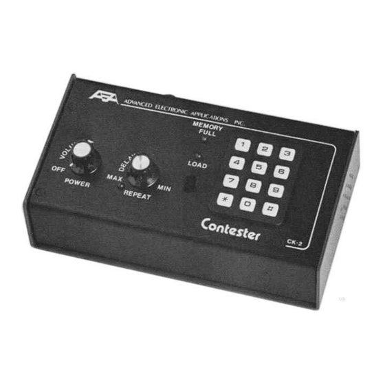
TOP PANEL DESCRIPTION REAR PANEL DESCRIPTION HOOK-UP INSTRUCTIONS... -
Page 5: Power
To Perform the Check-Out Procedures in the following section and familiarize yourself with the CK-2 it is first necessary to apply 13 volts to the power input jack on the Rear Panel of the CK- 2. This may be easily accomplished by connecting the cord attached to the optional AC-1 or AC-2 wall adapter to the power socket on the Rear Panel of the CK-2. -
Page 6: Check-Out Procedure
3. Press [*][*][1] and hold [1]. The monitor tone will decrease in frequency. 4. Send a series of letters with the external paddle to "get a feel" for the perfect code the CK-2 produces. 5. Press [*][2][0][#][7] and send more Morse characters. Note that the length of the dots has short- ened by one half. -
Page 7: Memory Load Mode
Memory Load Mode 1. Many of the steps you went through in the KEYER SEND mode could be repeated in MEMORY LOAD mode. To enter the memory load mode set the memory switch to LOAD, and note the LED will come on. 2. -
Page 8: Automatic Message Repeat
Note that no additional character is transmitted until after you let up on the pad- dle /the first time) and then commence sending. When no characters have been manually sent for a period of time equal to the delay setting, the CK-2 will automatically start sending mes- sage 1 again. -
Page 9: Operating Instructions
OPERATING INSTRUCTIONS General The AEA Keyer Model CK-2 has been designed for the serious CW operator. It features a versatile memory load and edit capability, automatic serial number, rapid CW speed changes and full weight- ing control. Keyer Operation Speed Change and Set Two methods of CW speed control are available, variable and preset. -
Page 10: Dot-Dash Memory
If the dot-space ratio entered exceeds 1.5 or is less than 0.5, the ratio will be set to 1.0. The dash-space ratio is set to 3.0 on turn-on and is adjustable from 2.0 to 4.0. To change the dash ratio, enter [*][*][2] and the new dash ratio. Example: A dash-space ratio of 3.7 is desired;... -
Page 11: Memory Operation
Memory Operation Memory Locations The AEA CK-2 has ten separate, variable length memory locations. The total memory length is about 500 characters (the actual length is dependent on the length of the characters, the length and number of pauses, etc.), which may be divided into the ten locations in any fashion. Each memory location length is automatically adjusted during message loading. -
Page 12: Serial Number Load & Set
Serial Number Load and Set An automatically incremented serial number may be inserted anywhere in any of the ten mes- sages. It may also be inserted as many times as desired within a message. The serial number is incremented just as the message is completed. To insert the automatic serial number during the loading of a message press [*][0]. -
Page 13: Serial Numbers In Memory Send
Automatic Message Repeat Message Location The CK-2 will continuously repeat any message stored in memory location 1. Delay Interval The delay interval (time from completion to message to next beginning) can be set from approx- imately 2 seconds to 2 minutes with the REPEAT DELAY control knob. -
Page 14: Appendix A
APPENDIX A Common Character Set... -
Page 15: Appendix B
MM-1 appears to be sending too slowly, but many tapes on the market are actually sent faster than the labeled speed! Suffice it to say that it is the opinion of AEA that the MM-1 has the most ac-... -
Page 16: Abbreviated Instructions
ABBREVIATED INSTRUCTIONS MODE INSTRUCTION LIMITS / COMMENTS AT TURN ON KEYER: Code Speed [*][*][8][N][N] 02–99 in 1 WPM increments 20 WPM Increase [*][1] Tone 100 Hz to 2500 Hz 500 Hz Decrease [*][*][1] Dot-Space Ratio [*][2][N][#][N] 0.5–1.5 in 0.1 increments Dash-Space Ratio [*][*][2][N][#][N] 2.0–4.0 in 0.1 increments... -
Page 18: Schematic
DISABLE CW SIDETONE OR KEYPAD FEEDBACK TONE. If diode D1 is removed, the CW sidetone is disabled. It is recommended that one end of the diode be clipped and the diode be pushed away from the lead. Diode D2 supplies the keypad feedback tone and may be disabled in the same manner. -
Page 19: Ck-2 Parts List
¼ W, 5 %, Carbon Comp R22 ........1k8 ¼ W, 5 %, Carbon Comp U1 ........CD4044B U2 ........PD444C U3 ........AEA 1980 MMK U4 ........555 Timer U5 ........7805 Voltage regulator X1 ........4.000 MHz Xtal S1 ........Part of R4... -
Page 20: Technical Specifications
TECHNICAL SPECIFICATIONS Keyer speed range: 1 to 99 WPM CMOS Memory: 4096 bits (approximately 500 Morse characters) Keying output: Grid block –300 V, max. 30 mA max. Cathode/Transistor 300 V, max. 200 mA Serial number range: 01 to 9,999 Auto Repeat Delay range: approximately 1 second to 2 minutes Dot memory On/Off: program selectable...
Need help?
Do you have a question about the CK-2 and is the answer not in the manual?
Questions and answers