
Subscribe to Our Youtube Channel
Related Manuals for ESAB A2-A6 PEK


Summary of Contents for ESAB A2-A6 PEK
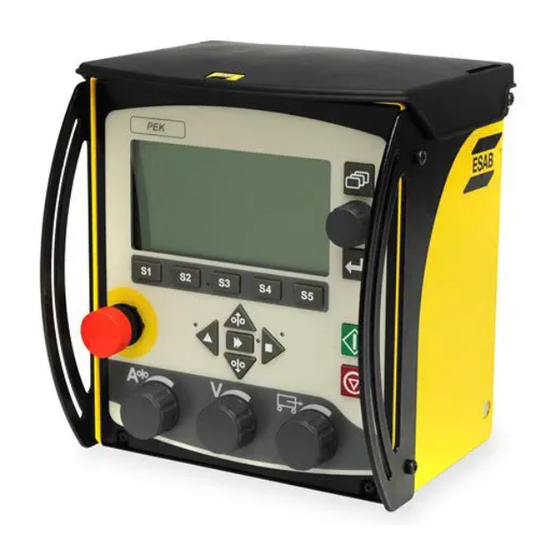
- Page 1 A2, A6 PEK Control Unit Service manual Valid for: serial no. 921-, 943-, 049-, 327-, 628-xxx-xxxx 0740 801 028 GB 20171110...
-
Page 2: Table Of Contents
26AP2:1 Power supply ................. 26AP2:2 Motor 1 drive (Wire feed at CN7)........... 26AP2:3 Motor 2 drive (Travel motion at CN6) ........26AP2:4 Relay outputs................. 26AP2 Circuit board versions ............... 26AP2 Component positions ..............0740 801 028 © ESAB AB 2017... - Page 3 Service aid ....................Replacing the battery ................SOFTWARE UPDATE................Motor control 26AP1 ................Welding data unit 1AP1................Updating software ................Reset with reset.txt ................SPARE PARTS ..................Rights reserved to alter specifications without notice. 0740 801 028 © ESAB AB 2017...
-
Page 4: Read This First
The manual is valid for PEK with serial number 921-xxx-xxxx, 943-xxx-xxxx, 049-xxx-xxxx, 327-xxx-xxxx and 628-xxx-xxxx. NOTE! The unit is tested by ESAB in a general set-up. The responsibility for safety and function, of the specific set-up, lies with the integrator. CAUTION! Read and understand the instruction manual before installing or operating. -
Page 5: Introduction
• limit switches • the ESAB WeldCloud™ Mobile unit (via Ethernet connection) (from serial no. 628-xxx-xxxx) 1AP1 MMC module The control unit has an MMC with processor, memory, control buttons and a display. The MMC is connected to the welding power source and the motor control board with a 500 kbit/s CAN bus. - Page 6 The motor driver board is supplied with 42 VAC from the welding power source via a rectifier. It has two H-bridge motor driver circuits making it possible to reverse the motors. The board also holds the relay that controls flux or gas. 0740 801 028 - 6 - © ESAB AB 2017...
-
Page 7: Wiring Diagram
X6.B, X6.C, X9.F, X1.G, XB.H CAUTION! STATIC ELECTRICITY can damage circuit boards and electronic components. • Observe precautions for handling electrostatic sensitive devices. • Use proper static-proof bags and boxes. 0740 801 028 - 7 - © ESAB AB 2017... -
Page 8: A2, A6 Pek Control Unit, Serial No. 921-, 943-, 049-, 327-Xxx-Xxxx
WIRING DIAGRAM A2, A6 PEK Control Unit, Serial no. 921-, 943-, 049-, 327-xxx-xxxx Updates: From serial no. 921-010-XXXX: Cable 18.1 removed From serial no. 921-010-XXXX: Wire jumper X1:12 to X1:15 introduced 0740 801 028 - 8 - © ESAB AB 2017... - Page 9 WIRING DIAGRAM 0740 801 028 - 9 - © ESAB AB 2017...
-
Page 10: A2, A6 Pek Control Unit, Serial No. 628-Xxx-Xxxx
WIRING DIAGRAM A2, A6 PEK Control Unit, Serial no. 628-xxx-xxxx 0740 801 028 - 10 - © ESAB AB 2017... - Page 11 WIRING DIAGRAM 0740 801 028 - 11 - © ESAB AB 2017...
-
Page 12: Technical Data
TECHNICAL DATA TECHNICAL DATA Supply voltage 42 V, 50/60 Hz Power requirement Max 900 VA Engine connections adapted for ESAB's 6 A 100% motors Speed control Feedback from pulse encoder Operating temperature -15°C to +45°C Transportation temperature -20°C to +55°C... -
Page 13: Installation And Connections
Connection for the welding power source with 42 VAC power supply, arc voltage feedback, emergency stop and CAN bus. NOTE! To prevent damage to the equipment ensure that the right type of cable is used. 0740 801 028 - 13 - © ESAB AB 2017... - Page 14 From serial no. 628-xxx-xxxx the PEK control unit is equipped with an Ethernet interface to be able to connect the unit to an ESAB WeldCloud™ Mobile unit. For further information about the WeldCloud™ system, see the WeldCloud™ instruction manual. For further information about the WeldCloud™...
-
Page 15: Internal Connections
42VAC, arc voltage encoder and emergency stop CN19, CN20 Voltage selection for CN7 Connection for motor (wire feed) encoders CN17 Connection for wire feed pulse CN6 Connection for motor (travel motion) encoder 0740 801 028 - 15 - © ESAB AB 2017... - Page 16 Emergency stop, 2nd circuit This circuit is not connected inside the unit. It can be used to control other units that require a separated emergency circuit. Emergency stop, 2nd circuit connections 0740 801 028 - 16 - © ESAB AB 2017...
- Page 17 • Disconnect the cable between X1:12 and X1:15 Example, connection of optional equipment • Connect optional equipment to terminal block X1 at 15 and 16. 0740 801 028 - 17 - © ESAB AB 2017...
- Page 18 Use the soft button called “Relay 2”. • Connect to terminal block X1 at 16 (+24 V). • Connect to terminal block X1 at 20 (0 V). 0740 801 028 - 18 - © ESAB AB 2017...
- Page 19 Power connection to motor 1 and 2 There are outputs to drive two motors. The motors are connected directly to the 26AP2 motor drive board with an ESAB accessory cable. Motor 1 for wire feed, connect to CN7. Motor 2 for travel, connect to CN6.
- Page 20 There are two inputs for reading motion. The inputs are designed for incremental quadrature encoders with a supply voltage of 5, 15 or 24 VDC. The encoders are connected directly to the 26AP1 motor control board with an ESAB accessory cable.
- Page 21 • Insert a cable fitting with strain relief into the hole. • Insert cable and secure it with the strain relief at the cable fitting. • Connect the cable to terminal block X1 at 9. Arc voltage 0740 801 028 - 21 - © ESAB AB 2017...
- Page 22 • Insert a cable fitting with strain relief into the hole. • Insert cable and secure it with the strain relief at the cable fitting. • Connect the cable to terminal block X1 at 3 and 5. 42 VAC Output 0740 801 028 - 22 - © ESAB AB 2017...
-
Page 23: Description Of Operation
The ID numbers of the circuit board in a PEK unit are: • Machine ID = 44. • Node id = 8. If used as PAB: • Machine ID = 46. • Node id = 8. 0740 801 028 - 23 - © ESAB AB 2017... -
Page 24: 1Ap1:1 Power Supply And Can Bus
At the end of the test the current software version is displayed briefly. After the self-test is finished, the display shows the measurment menu. 1AP1:1 Power supply and CAN bus Circuit diagram for the power supply 0740 801 028 - 24 - © ESAB AB 2017... - Page 25 To prohibit memory loss when the power to the unit is turned off, the battery must as soon as possible be replaced with a new one, if the voltage has dropped below 2.4 V 0740 801 028 - 25 - © ESAB AB 2017...
-
Page 26: Can Bus & Termination
When the board has been initiated, and is running the application program, LED D4 flashes continously with a green light. LEDs on welding data board 1AP1 LED D7 is not used in this application. 0740 801 028 - 26 - © ESAB AB 2017... -
Page 27: 1Ap1:2 Display Control
3 minutes, if the MMC unit is not in use. 1AP1:3 Pushbutton monitoring The control panel, 1AP3, includes a matrix with the front panel pushhbuttons Circuit diagram for control panel pushbuttons 0740 801 028 - 27 - © ESAB AB 2017... -
Page 28: Buzzer
USB connector. NOTE! The internal memory is named “A:\ ” and the USB memory is named “C:\ ” in the file manager of the unit. Circuit diagram for USB connection 0740 801 028 - 28 - © ESAB AB 2017... -
Page 29: 1Ap1:5 Encoder Monitoring
One square wave pulse is used as clock frequency and the other square wave pulse defines the knob-turning direction by comparing the phase position (positive or negative) compared to the clock frequency. Circuit diagram for encoder monitoring 0740 801 028 - 29 - © ESAB AB 2017... -
Page 30: 1Ap1:6 Ethernet Interface, From Serial No. 628-Xxx-Xxxx
DESCRIPTION OF OPERATION 1AP1:6 Ethernet interface, from serial no. 628-xxx-xxxx Circuit diagram for Ethernet interface 0740 801 028 - 30 - © ESAB AB 2017... -
Page 31: 1Ap1:7 Usb-Host B (Internal), From Serial No. 628-Xxx-Xxxx
This connector, USB-host B, is only accessible from inside the unit. It is located on the MMC/Welding data board 1AP1 and designated CN17. Connector CN16 is connected in parallel with connector CN17. Circuit diagram for USB-host B (internal) 0740 801 028 - 31 - © ESAB AB 2017... -
Page 32: 1Ap1 Component Positions
DESCRIPTION OF OPERATION 1AP1 Component positions Component positions for the welding data board, up to and including serial no. 327-xxx-xxxx 0740 801 028 - 32 - © ESAB AB 2017... - Page 33 DESCRIPTION OF OPERATION Component positions for the welding data board, from serial no. 628-xxx-xxxx 0740 801 028 - 33 - © ESAB AB 2017...
-
Page 34: 26 Motor Control & Motor Drive
-15 V ±1 V VR1:3 +15 V ±1 V CN19:3 +5 V ±0.2 V CN19:2 +2.5 V ±0.1 V CN25:1 You can see the measuring points in “26AP1 Component positions”, page 39. 0740 801 028 - 34 - © ESAB AB 2017... -
Page 35: 26Ap1:2 Can Bus & Termination
LED D10 flashes continously with a green light. LED D13 is not used for any function. LEDs on circuit board 26AP1 0740 801 028 - 35 - © ESAB AB 2017... -
Page 36: 26Ap1:3 Encoder For Wire Feed Motor
During rotation there are pulses at terminals CN17:3 and 4. The pulse frequency is a measure of the speed. The phase relation between the two pulse trains gives the direction of rotation. 0740 801 028 - 36 - © ESAB AB 2017... -
Page 37: 26Ap1:4 Encoder For Travel Motor
26AP1:5 Travel limit switches The external limit swiches are connected to terminal block X1 at 11,12,13 and 14. The status of the switches is checked by the processor on 26AP1 via an optocoupler. 0740 801 028 - 37 - © ESAB AB 2017... -
Page 38: 26Ap1:6 Laser Lamp Supply
The 5 V laser lamp connection is not recommended, see "Laser lamp supply 24 V" in “Internal connections”, page 15. 26AP1:7 External Start/Stop switch An external switch can be connected to X1:10 and used as external weld Start/Stop signal. 0740 801 028 - 38 - © ESAB AB 2017... -
Page 39: 26Ap1 Component Positions
DESCRIPTION OF OPERATION 26AP1 Component positions 0740 801 028 - 39 - © ESAB AB 2017... -
Page 40: 26Ap2 Motor Drive
On the board it generates a 24V ±1 V and this voltage is used internally on the board and is also supplied to 26AP1. The motor control board, 26AP1, supplies +15 V, -15 V and +5 V to the motor drive board, 26AP2. 0740 801 028 - 40 - © ESAB AB 2017... -
Page 41: 26Ap2:2 Motor 1 Drive (Wire Feed At Cn7)
DESCRIPTION OF OPERATION 26AP2:2 Motor 1 drive (Wire feed at CN7) 0740 801 028 - 41 - © ESAB AB 2017... - Page 42 The relationship between the signal and the motors voltage is: Umeas = 2.5 + (0,241 * Imotor) eg: 1.3 V = -5 A, 2.5 V = 0A, 3. 7V = 5 A measured between CN2:4 and CN2:7-8 0740 801 028 - 42 - © ESAB AB 2017...
-
Page 43: 26Ap2:3 Motor 2 Drive (Travel Motion At Cn6)
DESCRIPTION OF OPERATION 26AP2:3 Motor 2 drive (Travel motion at CN6) 0740 801 028 - 43 - © ESAB AB 2017... -
Page 44: 26Ap2:4 Relay Outputs
26AP1 are connected to driver circuits on 26AP2. The control signal is amplified by two transistors connected to a relay. The outputs of the relays are galvanic separated from the electronics and available at X1:15/16 and X1:17/18. 0740 801 028 - 44 - © ESAB AB 2017... -
Page 45: 26Ap2 Circuit Board Versions
The spare parts list is updated with ordering number for the new board. More information on this issue and a field update instruction is available in Service Information Si101222 (can be downloaded from www.esab.com/login/). 0740 801 028 - 45 -... -
Page 46: 26Ap2 Component Positions
DESCRIPTION OF OPERATION 26AP2 Component positions 0740 801 028 - 46 - © ESAB AB 2017... -
Page 47: Fault Codes
DELETE. To delete all error messages from the fault log, press the soft pushbutton DELETE ALL. This action will erase all messages from the fault log. 0740 801 028 - 47 - © ESAB AB 2017... -
Page 48: Error Code Description
Error code from external source. To low current detected during 0.3 sec and welding is interrupted. Action: Check if something obstruct the welding arc, check for faulty cables. Check manual for connected units 0740 801 028 - 48 - © ESAB AB 2017... - Page 49 If this error appers directly after installing a PEK, check jumper settings inside the power source. In LAF/TAF power sources: On the AP1 board remove jumper at CN18 from pin 1-2 and connect it only to pin 3. 0740 801 028 - 49 - © ESAB AB 2017...
- Page 50 The program restarts automatically. The current welding process will be stopped. This fault does not disable any functions. Action: This fault should not happen. Contact ESAB if the fault yet occurs. Faulty wire configuration Action: PAB user, check wire and dimension settings.
- Page 51 Action: Check the voltage frequency. Power source control board processor fault Action: Contact the ESAB Global Service Helpdesk. 173 External stop activated from external equipment via I/O unit 181 Incorrect loading files when a whole system was to be updated via USB Action: Check loading files and use compatible files.
- Page 52 420D Power block sensor lost 420E AC block 1 sensor lost 420F AC block 2 sensor lost 5001 Internal flash error in power source control board Action: Replace the power source control board. 0740 801 028 - 52 - © ESAB AB 2017...
- Page 53 5010 Inductance to high Action: Check the length of the welding cables or try welding using a lower current. 6101 Watchdog error Action: Contact the ESAB Global Service Helpdesk. 6103 Flash Action: Replace the power source control board. 8100 Communication error (warning) The load on the system's internal CAN bus is temporarily too high.
- Page 54 F008 AC unit F009 AC unit warning F00A Supply voltage dip Action: Check the stability of the supply voltage. F00B Power supply fail Action: Check the stability of the supply voltage. 0740 801 028 - 54 - © ESAB AB 2017...
-
Page 55: Service Instructions
Overall, handling of ESD-sensitive devices should be minimized to prevent damage. Service aid ESAB can offer a number of service tools that will simplify the service. Antistatic service kit Ordering no. 0740 511 001 The kit makes it easier to protect sensitive components from electrostatic discharge. -
Page 56: Replacing The Battery
The software update is made from a PC, it has to be managed by a trained serviceman. For this a PC program called ESAT, ESAB Software Administration Tool, is needed. The PC is connected to the welding equipment by a cable connector and a CAN reader. From the ESAT it is possible to update the software. -
Page 57: Software Update
“update.txt_”. If the USB memory still is connected at the next power on, a new upgrade is then prevented. Before the USB memory stick can be used for update of another unit the text file must be edited by a computer back to: ”update.txt”. 0740 801 028 - 57 - © ESAB AB 2017... - Page 58 The new software release New software realeases are distributed through the ESAB service network. The boot program in the PEK, used for the upgrade, has support for software files ending with: *.hex...
- Page 59 Set CAN bus bauderate to 400 kbit/s. Set node adress (node id) Line Comment 30 0 0 8 0 255 Set the node address to 8, use for (PEK and PAB unit). 0740 801 028 - 59 - © ESAB AB 2017...
-
Page 60: Updating Software
USB memory (see Export/Import in the users manual for the PEK control panel). 2. By means of a computer, save the new software (firmware) to another empty USB memory stick. 0740 801 028 - 60 - © ESAB AB 2017... -
Page 61: Reset With Reset.txt
3. Check that the USB memory contains the file “reset.txt” (see “The file “reset.txt””, page 58). 4. Turn off the power source's main switch. 5. Insert the USB memory with the file “reset.txt”, into the USB connector. 0740 801 028 - 61 - © ESAB AB 2017... - Page 62 11. The reset of the unit is now finished. 12. If preferred, import the backed-up welding data from the USB memory into the unit's memory (see Export/Import in the user manual for the unit). 0740 801 028 - 62 - © ESAB AB 2017...
-
Page 63: Spare Parts
SPARE PARTS SPARE PARTS The spare parts list is published in a separate document that can be downloaded from the Internet: www.esab.com Filename Product 0459 839 036 0740 801 028 - 63 - © ESAB AB 2017... - Page 64 ESAB subsidiaries and representative offices Europe THE NETHERLANDS North and South America SOUTH KOREA ESAB Nederland B.V. ESAB SeAH Corporation AUSTRIA Amersfoort ARGENTINA Kyungnam ESAB Ges.m.b.H Tel: +31 33 422 35 55 CONARCO Tel: +82 55 269 8170 Vienna-Liesing Fax: +31 33 422 35 44...
Need help?
Do you have a question about the A2-A6 PEK and is the answer not in the manual?
Questions and answers