Table of Contents
Advertisement
Quick Links
Solidremote 202U 2-Channel Stand Alone Receiver Instructions
Thank you for purchasing Solidremote 202U 2-channel stand alone
receiver. Familiarise yourself with the following instructions prior to
commencing set up. Store this information in a safe place for future
reference.
Short Introduction
202U receiver has two relays on board which provide normally open
& normally closed voltage-free dry contact (doesn't output power)
for controlling virtually any electronic device. In default standard
mode, both relays can be set to any of three modes – pulse
(momentary), hold (toggle) or interlock latching using DIP switches.
Setting Relay Operation in Standard Mode
Pulse / Momentary – Relay contact is active whilst transmitter
button is pressed, min. active period is ~0.5s
Hold / Toggle – Relay changes state at each press of transmtter
button. Hold, Release, Hold etc. (like an on/off switch)
Interlock Latching – Two relays interact with each other, Relay 1 on
then Relay 2 off, Relay 2 on then Relay 1 off. (useful in small DC
motor reverse polarity control)
DIP Switch 1
ON
DIP Switch 2
ON
↓
with DIP Switch 3 OFF
Relay 1
Pulse
Relay 2
Hold
To turn off both relays in this mode, press the special function
button which is assigned to both relays 1&2 (programmed by press
both PRG1 & PRG2 when storing transmitter code).
Storing Transmitter Code
1. Press and hold PRG1 (for Relay 1) or PRG2 (for Relay 2) or
PRG1 and PRG2 (for both Relay 1 & 2) until SIG LED turned on.
2. Press the transmitter button you would like to control the channel
once until SIG LED flashes, then release transmitter button.
3. The SIG LED will flash quickly three times, indicating that the
code has been stored.
4. Release all PRG button on receiver.
5. Press the programmed transmitter button to test operation.
ALWAYS post a new topic in forum & double check email for prompt response, thanks.
ON
OFF
OFF
OFF
ON
OFF
Hold
Interlock
Pulse
Hold
Latching
Pulse
Visit solidremote.help if you need help
Remove Single Transmitter Code: Repeat steps 1-5 above. During
removal process, SIG LED on step 3 will flash slowly three times
(instead of quickly), indicating that the code has been removed.
Deleting All Stored Transmitter Codes
1. Turn power off to receiver.
2. Press and hold both PRG1 and PRG2 button.
3. While holding both PRG1 and PRG2 - turn power on again. After
5 seconds the SIG LED will illuminate to indicate receivers memory
has been cleared.
4. Release PRG1 and PRG2. All the stored codes should now be
deleted. Confirm this by pressing transmitters previously used to
operate the device. There should be no response.
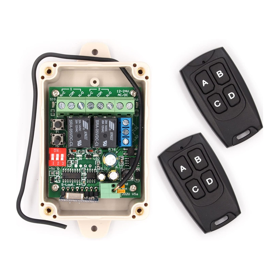
Receiver Function Diagram
Signal LED
Learn Button
Mode Select
+5V MagicPort
Receiver Module
Technical Specifications
Power Supply: 9V-24V AC or 9V-30V DC
Frequency: 433.92MHz OOK
Memory Capacity: 510 Transmitters (up to 14 buttons each)
Antenna Impedance: 50 Ohms (RG58)
✔
Relay Contact Rating:
Resistive Load (cosΦ=1): 10A @ 14V DC or 10A @ 120V AC
Inductive Load (cosΦ=0.4 L/R=7msec): 6A @ 14VDC
Temperature Rating: -4°F to 131°F (-20°C to 55°C)
Weight: 0.25 lbs. (0.11kg)
Physical Size: 4.33"L x 2.36"W x 1.37"H (11cmL x 6cmW x 3.5cmH)
Power LED
Terminal
Limit Switch
2 x Relay
Relay LED
MCU
Power
Supply
--- Page
1
Advertisement
Table of Contents

Related Manuals for Solidremote 202U

Summary of Contents for Solidremote 202U
- Page 1 Deleting All Stored Transmitter Codes Short Introduction 1. Turn power off to receiver. 202U receiver has two relays on board which provide normally open 2. Press and hold both PRG1 and PRG2 button. & normally closed voltage-free dry contact (doesn’t output power) 3.
- Page 2 DC jack to screw or it may cause unexpected results or damage. terminals converter Following examples are using 202U’s Relay 1 for wiring, you can use Relay 2 of course, the idea is the same. Basic wiring using separate power supplies The following is a simple wiring diagram for controlling light bulb on &...
- Page 3 The following section may seems complex (not easy to use), especially for first time users. It’s because we try to put as many features as possible based on current hardware. If you only use basic features (same as previous 202U versions), then just SKIP the following section, thanks. Discover new features in V5 - Settings To make full use of current hardware, and make our receiver as versatile as possible, we have introduced settings in V5 version.
- Page 4 ✔ This setting does NOT affect timed output mode. Visit solidremote.help if you need help --- Page ALWAYS post a new topic in forum & double check email for prompt response, thanks.
- Page 5 It should be good enough for common purpose, but NOT SUITABLE for applications that requires very precise timing control. Visit solidremote.help if you need help --- Page ALWAYS post a new topic in forum & double check email for prompt response, thanks.
Need help?
Do you have a question about the 202U and is the answer not in the manual?
Questions and answers