Table of Contents
Advertisement
Advertisement
Table of Contents

Related Manuals for Solidremote 402U

Summary of Contents for Solidremote 402U
-
Page 1: Installation Manual
Solidremote 402U Wireless Receiver Installation Manual Edition_A1... - Page 2 Thank you for purchasing Solidremote 402U standalone receiver with SolidAdvantage. Familiarise yourself with the following instructions prior to commencing setup. Store this information in a safe place for future reference. Part of 4 generation 40X receiver family, 402U is by far the best 2Ch wireless receiver made by us. It...
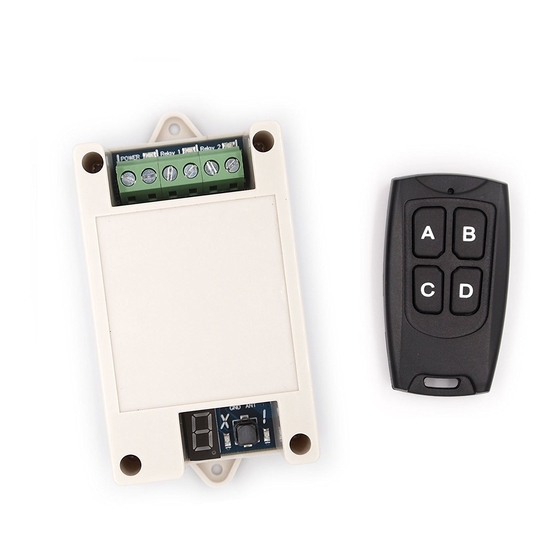
- Page 3 At a Glance 402U wireless receiver has two relays on board which provide normally open (NO) dry contact for controlling virtually any electronic device. Both independent relays can be programmed to any of three modes - pulse, hold or latching.
-
Page 4: Compatible Transmitters
Compatible Transmitters 402U Rev. A receiver works with all Solidremote TrioAES 433 mainstream transmitters and TrioAES 433-X transmitters with eXtended range. With Solidremote’s TrioAES technology, traditional code grabbers are blocked outside because our RF code and frequency change continuously in transmission. - Page 5 Receiver PCB Feature Map POWER Relay 1 Relay 2 Terminals Relay Power RF Module...
- Page 6 Remove top cover of the receiver to access DIP switches, beeper on/off jumper and antenna ports. Part # Description ① ON - Receiver is up and running Power ② ON - Relay 1 activated Relay 1 ③ ON - Relay 2 activated Relay 2 ④...
- Page 7 ⑥ ON - Entered programming, erasing or reporting # mode 7-Segment Display † In following pages, LED refers to 7-segment LED display unless otherwise specified. ⑦ Serving as audio aids, beeper will usually sound when LED changes. Beeper It can be particularly useful when receiver is placed out of sight.
- Page 8 It looks like two relays interact with each other on 402U receiver, relay 1 on then relay 2 off, relay 2 on then relay 1 off. An ~300ms delay is implemented by design to ease...
- Page 9 Advanced working modes such as timed output and sequenced output are possible via ODM order. DIP # 1 DIP # 2 ↓ Pulse Hold Latching Pulse Relay 1 Hold Hold Latching Pulse Relay 2 † Relay 1&2 are two onboard relays, while relay 3&4 are virtual relays which follow relay 1&2’s operating mode respectively (3→1 / 4→2), except for latching mode, where any transmitter button...
- Page 10 LED turned off immediately. Solidremote’s Smart Range feature automatically limit receiver’s range during programming & erasing (except in remote learning), this is to avoid interference from unwanted transmitters far away.
- Page 11 Storing / Programming Mode Usage Number on left side indicates which relay you would like to program into. 1&2 are for two onboard relays, while 3&4 are for virtual relay ports, see 6X Expansion Ports section for usage on latter 1.
- Page 12 repeat the above steps 1-2. 4. Wait 10 seconds until receiver LED turned off, you can press the transmitter button to test operation. A (ALL) is for whole transmitter learning instead of button by button, storing procedure is same as above steps 1-4, except for that press any transmitter button will memorize the whole transmitter, then button will...
- Page 13 Erasing Mode Press any button on transmitter will erase all memorized buttons on that transmitter. LED dot flashes quickly indicates that all codes associated with that transmitter are now erased. Reporting # Mode No transmitter is required under this working mode Wait 10 seconds while LED dot flashes, then it will show how many memory slots are occupied by now.
- Page 14 2. 402U Rev. A has 80 memory slots in total, if you attempt to store new transmitter button when memory is already full, it will be refused by receiver...
- Page 15 Erasing All Stored Transmitter Codes 1. Turn power off to receiver. 2. Press and hold PRG button. 3. While holding PRG button turn power back on, LED will count down from 5 to zero in 5 seconds. After that LED will show flashing while erasing in progress, LED will turn off after all receiver memory has been cleared, usually...
- Page 16 Remote Learning Procedure Remote learning makes it easy for you to store new transmitters over-the-air, without touching PRG button on receiver, it is particularly useful if receiver is located somewhere difficult to access. DIP # 3 must be turned ON to enable remote learning feature, remote learning is disabled by default to provide maximum security.
- Page 17 2. Within 5 seconds, press ASSOC button again for one second then release. — 3. LED will turn on to show with flashing dot. 4. Within 10 seconds, select relay channel for programming by pressing an already assigned button on master transmitter for one second then release.
-
Page 18: Mode Introduction
X Mode Introduction X (eXtended) mode is designed to achieve even better range and stability by fine-tuning receiver to increase sensitivity by 4dBm. ⚠ X mode works with TrioAES 433-X transmitters only, using it on TrioAES 433 transmitters will result in extremely worse range. DIP # 4 must be turned ON to enable X mode, only turn on DIP # 4 when you solely use X mode transmitters with receiver, default setting is OFF. -
Page 19: Expansion Ports
6X Expansion Ports P1 P2 P3 P4 P5 P6 ○ ○ ○ ○ ○ ○ Port # Function +5VDC output, up to 150mA current Virtual relay (P2→R3 / P3→R4) active low transistor ground output, max 300mA sunk each port 0V GND Onboard relay limit switch input (P5→R1 / P6→R2), relay releases when port connected to P4... -
Page 20: Technical Specifications
Technical Specifications or 9-40V DC Power Supply Voltage: 9-28V AC Standby Current: 21mA at 12VDC / 11mA at 24VDC / 9mA at 30VDC Working Current: +60mA each activated relay at 12VDC / +40mA beeper sound at 12VDC Frequency: 3 frequencies hopping near 433MHz Memory Capacity: 80 transmitter button codes Antenna Connector: 22-14AWG screw terminal or industry standard u.FL... - Page 21 Weight: 0.16 lbs. (0.07 kg) Physical Size: 3.82"L x 1.98"W x 1.24"H (9.7cmL x 5.04cmW x 3.14cmH) Power & Relay Terminals: 10A screw terminals / fit 22-12AWG wire with min. 6mm stripped Beeper: 85dB sound level at 10cm distance 1. If you’re using transformer to get AC power, make sure measure the real voltage output of transformer before use, since sometimes a labelled 24VAC transformer can get you 30VAC due to...
-
Page 22: Basic Installation Guidelines
Basic Installation Guidelines Installation plays an important role in achieving optimum performance, here are some recommendations that may help. 1. Mount the receiver in a location where it is not exposed to weather or moisture, and where it is not surrounded by metal. - Page 23 Motors and other electronic devices may cause radio frequency interference (RFI) and power line noise that could impair the performance of a radio controlled device like 402U. For best results, locate the receiver away from other electronic devices and connect the receiver to a clean power source such as standard 9-24V power supply (AC or DC) or battery pack.
-
Page 24: Sample Installation
Sample Installation #1 Use 402U receiver to control a 110VAC light bulb, using independent power sources. 9-40V DC / 9-28V AC output w/ DC jack to screw terminals converter 110VAC... - Page 25 Sample Installation #2 Use 402U receiver to control a 12VDC electronic siren, using shared power source 12V DC output Due to siren req. w/ DC jack to screw terminals converter 110VAC 1. Not recommended for motor or other electronics which will introduce noise into power line.
-
Page 26: Troubleshooting
Troubleshooting When installing 402U wireless receiver, if it is not working properly here is a basic method to troubleshoot the products. 1. When transmitter button is actuated, does the transmitter LED illuminate? > If yes, proceed to step 2. > If no, check the battery and make sure battery is connected to the transmitter properly and battery is not flat. - Page 27 Ensure that correct power (see technical specs above) is supplied to the power terminal of 402U receiver, and the wiring harness is plugged in correctly. Refer to POWER label next to terminals to locate the two power terminals. ⚠ It is important to know that the transmitter must have been learned to receiver before proceed to following steps.
- Page 28 4. If receiver is not responding to a signal from transmitter, there are a few additional things to consider. > Materials such as metal, energy efficient (Low E) glass or other electronic devices may affect the signal. If possible, hold transmitter near receiver and activate it.
- Page 29 Ensure that the output terminal of receiver is connected properly to target circuits or devices. If you still have questions, please contact us via Amazon or post on solidremote.help, our support staff is more than happy to help.
-
Page 30: Hardware Revision History
Hardware Revision History The revision and product identifier of 402U boards are printed at one corner on top side of PCB, in plain text as nnnn Rcvr Rev. rr where nnnn is the identifier and rr is the revision. Rev. A - Product initial release / 2017... -
Page 31: Special Notice
Special Notice The descriptions and illustrations contained in the present manual are not binding. Solidremote reserves the right to make any alterations deemed appropriate for the technical, manufacturing and commercial improvement of the product, while leaving its essential features unchanged, at any time and without undertaking to update the present publication. - Page 32 Solidremote Technologies Ltd www.solidremote.com Factory Add: Bldg 4, Huamei Industrial Park, Buji Town, Longgang District, Shenzhen 518112, China DOCID: SR-RCS-402U-170124 / Printed In China ♲ Printed on Recycled Paper...
Need help?
Do you have a question about the 402U and is the answer not in the manual?
Questions and answers