Table of Contents
Advertisement
Quick Links
Advertisement
Table of Contents

Related Manuals for ParTech 7300w2 Monitor


Summary of Contents for ParTech 7300w2 Monitor
- Page 1 INSTRUCTION MANUAL 7300w² Monitor Issue 22...
- Page 2 7300w² Monitor Instruction Manual ** This page is intentionally left blank ** Page 2 of 46 224081IM Issue 22 Issue Date 27/03/2018...
-
Page 3: Table Of Contents
7300w² Monitor Instruction Manual Table of Contents 1 Foreword..................................5 1.1 Manual Conventions..............................6 1.2 WaterWatch² Trademark............................6 1.3 Scope of Manual..............................6 1.4 External Sensors..............................6 2 Safety Precautions................................7 2.1 General..................................7 2.2 Electrical Installation..............................7 2.3 Operating................................. 7 2.4 Service and Maintenance............................ - Page 4 7300w² Monitor Instruction Manual 5.3.8 Measurement Status........................... 26 5.3.9 Add Measurement............................27 5.3.10 Measurement Removal..........................27 5.4 Measurement (Specific) Config..........................27 5.4.1 Display Position............................27 5.5 Alarm Config (Relay outputs)..........................28 5.5.1 Alarm Addressing with Expansion Boxes....................29 5.6 Output Config (Analogue Outputs)........................30 5.6.1 Output Addressing with Expansion Boxes....................31 5.7 Information................................
-
Page 5: Foreword
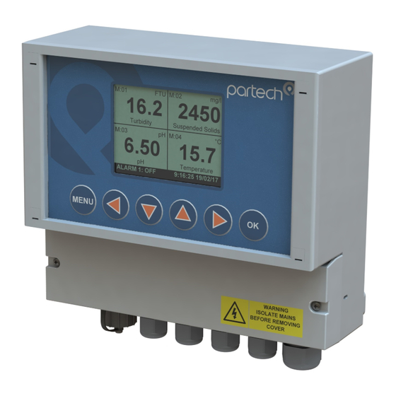
7300w² Monitor Instruction Manual 1 Foreword 7300w² Monitor is the “Operator Interface” to the WaterWatch² family of measuring instruments and sensors, and has been developed to be the successor to the very popular WaterWatch'1' and 7200 Monitors. Using the latest embedded processor technology, the 7300w² Monitor has been designed to encompass an easy to use and intuitive interface while providing advanced features and communication protocols to satisfy the most demanding of applications and environments. -
Page 6: Manual Conventions
Training in the use of the 7300w² Monitor and sensors can be provided, please contact Partech for further information. Icons have been used throughout this manual to draw your attention to precautions and useful notes. -
Page 7: Safety Precautions
Please check the correct voltage is applied to the monitor before making live. Incorrect supply voltage can cause damage to the 7300w² Monitor. Only connect sensors from the w² range to this monitor, other Partech products without the w² reference are not compatible and may cause damage if connected. IF IN DOUBT, PLEASE ASK. -
Page 8: Service And Maintenance
Maintenance for the 7300w² Monitor should be carried out as specified in this instruction manual. Failure to carry out regular maintenance could invalidate the Warranty. Services and repairs must be carried out by a Partech engineer. Partech can provide a service contract for your system. Please ask for details. -
Page 9: Installation
Whilst all attempts have been made to ensure that these instructions are correct, common sense and good engineering practice should always be used, as every installation can present a new set of challenges and difficulties. If you are in any doubt please contact Partech or your local distributor for further information. 4.1 Mechanical Installation Monitor external dimensions. -
Page 10: Fixings
7300w² Monitor Instruction Manual Fixings The 7300w² Monitor has 3 fixing points for mounting. Follow these instructions for easy installation and mounting. Offer the monitor up to the final mounting position. Mark the wall behind with a dot halfway along the •... -
Page 11: Electrical Installation
7300w² Monitor Instruction Manual 4.4 Electrical Installation Unscrew the two cover screws on the lower panel of the 7300w² Monitor to reveal the Terminals. Each terminal strip is labelled as illustrated below. (This equipment must be isolated or disconnected from HAZARDOUS LIVE voltages before access). -
Page 12: Dc Power Connections
7300w² Monitor Instruction Manual 4.4.2 DC Power Connections The DC power connection is a 3 way terminal strip, located furthest right of the termination bank. The left terminal is the Positive (+) supply, the Right terminal is the Negative (-) or Zero voltage supply and the centre terminal is the Ground. -
Page 13: Extending Sensor Cables
Sensors are usually supplied with 10m cables (longer cables can be provided on request). These cables can be extended to a maximum length of 100m. To ensure optimum performance, we advise the use of Partech ModTechw² cable for extensions. Partech can supply Junction Boxes to allow for easy termination of cable extensions. -
Page 14: Relay Outputs (Alarms)
7300w² Monitor Instruction Manual 4.4.6 Relay Outputs (Alarms) The relay outputs are 3 way terminal strips, located in the middle of the termination bank. The 7300w² Monitor offers 3 SPCO relay contacts that are user configurable. Please refer to the “Alarm Configuration” section of this manual for details of how to configure the relays for alarms or process control outputs. - Page 15 12VDC 2A min, and connects to the “EXT PWR” terminal of the Expansion Box. A suitable power supply is available from Partech. See the Data sheet supplied with each expansion box for full configuration details.
- Page 16 7300w² Monitor Instruction Manual Example of a typical 8x Input and 8x Output Expansion Box installation Page 16 of 46 224081IM Issue 22 Issue Date 27/03/2018...
-
Page 17: Basic Operation
7300w² Monitor Instruction Manual Basic Operation 5.1 Keys and Screen Navigation All menus and parameter settings are accessed using the 7300w² Monitor membrane keypad. 5.1.1 Menu Button From the measurement display screen press to show the Main Menu. While in sub menus, acts as a return to the previous menu. -
Page 18: Trending Display Mode
7300w² Monitor Instruction Manual 5.3.1 Trending Display Mode The trending display always the data to be plotted against time. The data goes back 24 hours. Press to enable scrolling and zooming on the trending chart. Press the to scroll back and forth in time. Press to zoom in and out on the time axis. -
Page 19: System Configuration
7300w² Monitor Instruction Manual 6 System Configuration. From the Measurement Display press to enter the “MAIN MENU”. From this menu, all configurations and parameters are defined. Setting up the monitor is a simple and intuitive process. The menu structure has been designed to lead the operator through the configuration process. -
Page 20: Backlight
7300w² Monitor Instruction Manual 6.1.2 Backlight BACKLIGHT From the MONITOR CONFIG menu press to select Always Off BACKLIGHT. Always On ✓ On after keypress The backlight can be set to always ON, always OFF or ON after key press (backlight will switch off again after a period of inactivity). There is a marginal power saving by having the backlight switched off, otherwise this setting is down to user preference. -
Page 21: Enable Service Mode
Service mode allows the user access to diagnostic information and Enter Service Password detailed set-up parameters. This will normally be used under the guidance 00000 of a Partech engineer, see section 7. to set value Press OK to accept Press MENU to cancel 6.2 Expansion Config... -
Page 22: Expansion Box Config Menu
7300w² Monitor Instruction Manual 7. From the Expansion CONFIG screen, select the required EXPANSION CONFIG Expansion Box to be configured, e.g. “E:1 WW² EB 8A 8R” by Expansion Status pressing to highlight, then press . Select “E:0# Add Expansion Modbus Address” and press . -
Page 23: Expansion Box Pn224920 - Single Analogue Input
7300w² Monitor Instruction Manual Modbus address of the Expansion Box is changed as follows: E:01 MODBUS ADDRESS 1. From the EXPANSION CONFIG screen, use highlight the Expansion Box to be re-addressed i.e. “E:1 WW² EB 8A 8R”, then press to select. 2. -
Page 24: Sensor Config
7300w² Monitor Instruction Manual Sensor Config The monitor leaves the factory with no sensors pre-installed. Before attempting to configure a measurement, the sensor must be installed. At this stage it is worth reviewing the contents of the sensor manual(s) to ensure each sensor has been mechanically and electrically installed correctly. NOTE: Once the Sensors have been wired, unplug each 4-way connector from the 7300w²... -
Page 25: Sensor Removal
7300w² Monitor Instruction Manual 1. From the SENSOR CONFIG screen, use to highlight SENSOR CONFIG the sensor to be configured: e.g. “S:01 TurbiTechw² LR (0-30)”, Sensor Status then press to select. Add Sensor S:01 TurbiTech² LR (0-30) 2. Once selected, the CONFIG MENU will be displayed with specific parameters available for the sensor. -
Page 26: Default Modbus Addresses
7300w² Monitor Instruction Manual 6.3.6 Default Modbus Addresses Default Modbus Sensor / Expansion Box Address Reserved for system – DO NOT USE 1 to 8 User Defined (advise: use for sensors) User Defined (advise: use for Expansion Box) OxyTechw² OPT TurbiTechw²... -
Page 27: Add Measurement
7300w² Monitor Instruction Manual 6.3.9 Add Measurement MEASUREMENT CONFIG 1. From the MAIN MENU screen, select MEASUREMENT CONFIG Measurement Status by pressing , and press Add Measurement M:01 TurbiTech² LR NTU (S:01) 2. The MEASUREMENT MENU should be displayed. Press highlight ADD MEASUREMENT, and press 3. -
Page 28: Alarm Config (Relay Outputs)
7300w² Monitor Instruction Manual 3. The current display position will be shown, e.g. 1 for M:01 M:01 DISPLAY POSITION Turbidity. Press to move the cursor below the digit to be changed. 5. Press to increase or decrease the digit to the desired to set value new position (e.g. -
Page 29: Alarm Addressing With Expansion Boxes
7300w² Monitor Instruction Manual Type: Offers the following options: • ALARM 1 (M) CONFIG Alarm 1 (M) Value OFF: No relay output. Alarm 1 (M) Hysterisis Alarm 1 (M) Fault Setup LOW: Alarm active on a low reading (below the set point). Alarm 1 (M) Set Delay Alarm 1 (M) Reset Delay HIGH: Alarm active on a high reading (above the... -
Page 30: Output Config (Analogue Outputs)
7300w² Monitor Instruction Manual Output Config (Analogue Outputs) The 7300w² monitor leaves the factory without any outputs configured. Outputs can only be configured after installing the relevant sensor(s) and measurements(s). The default condition is OFF. Skip this section if you have no requirements for analogue outputs. OUTPUT CONFIG Output Status The OUTPUT CONFIG menu defines the functions of the 2 analogue... -
Page 31: Output Addressing With Expansion Boxes
Please have this information available if you need to Contact Information contact Partech about this product. 6.7.2 Contact Information This displays Partech's address, phone number and website URL. 224081IM Issue 22 Issue Date 27/03/2018 Page 31 of 46... -
Page 32: Lock Config
Care should be taken when changing the password. If the password is lost, it may be necessary for Partech to visit the instrument to unlock the monitor and reset the password. From the LOCK CONFIG menu press to select CHANGE PASSWORD and press This screen requests the OLD password. -
Page 33: Logging
7300w² Monitor Instruction Manual 6.9 Logging The 7300w² Monitor will automatically log the measurement values and status. This log file can then be saved on a USB memory stick for review on a PC. Monitor can store 10,000 records. The data will not be lost, even if the 7300 is powered down. - Page 34 Microsoft Excel or Open Office Calc. Measurement Status Opening the file should result in correctly formatted columns displaying the data. Sensor Status For details on decoding the status columns please contact Partech support. Page 34 of 46 224081IM Issue 22 Issue Date 27/03/2018...
-
Page 35: Service Mode
The 7300w² Monitor has a set of hidden menus that provide access to a wide range of diagnostic information and tools. These may be required when investigating faults with the Monitor or Sensors including detailed calibration information. These menus are intended for use by Partech engineers or engineers who have been provided with additional training. -
Page 36: Output 0/4Ma And 20Ma Offset
7300w² Monitor Instruction Manual This option allows the configuration of the on-board I/O of the monitor. These Inputs are not currently available to the user. 3. Digital Output Config This option allows the configuration of the on-board I/O of the monitor. These outputs are not currently available to the user. - Page 37 7300w² Monitor Instruction Manual Navigate to “20mA Offset” option as follows: Main Menu > Output Config > Output # Config > Output # (M) 20mA Offset First set the 4mA offset. Adjustment of the 4mA output will also effect the 20mA output, i.e. increasing the 4mA output by 0.5mA will also add 0.5mA to the 20mA output.
-
Page 38: Menu Tree
Menus in Blue are only available when an expansion box is connected. Menus in are intended for Partech Technicians only. Main Menu Hold Outputs (when Service Mode is enabled) Monitor Config Bleeper... - Page 39 7300w² Monitor Instruction Manual ((M) = refers to Monitor, whereas (E:1) refers to Expansion Box No.1) Output Status Output # Config Output # (M) Info Output # (M) Measurement Output # (M) Type Output # (M) 4mA Output # (M) 20mA Output # (M) Fault Mode Output # (M) Fault Setup Output # (M) Test...
-
Page 40: Maintenance
7300w² Monitor Instruction Manual Maintenance On-Board Battery Backup Replacement The monitor is fitted with a battery backup for the real time clock function. Failure of the battery will only effect the time (all parameters, settings and process data are stored electronically and is not effected by a failed battery). -
Page 41: Faults
Communication errors can be caused by faulty or poorly installed cable, please check the connections before taking any further action. If the problem persists, contact Partech or your local Partech representative. 10.2 Sensor Error Messages The majority of error messages displayed on the monitor will be reported by the sensor, these messages will vary between sensor type. -
Page 42: Technical Support
Digital photos can also be useful to determine correct installation and suitability to the application. • 11.1 Returning Equipment for Repair If equipment needs to be returned to Partech for repair or service the following address should be used: SERVICE DEPARTMENT PARTECH INSTRUMENTS ROCKHILL BUSINESS PARK... -
Page 43: Technical Specification
7300w² Monitor Instruction Manual 12 Technical Specification 12.1 Physical Dimensions ........213 x 185 x 95mm (HxWxD) Enclosure Material......Polycarbonate (PC) Weight..........1.4Kg Temperature........-20 to +60 C, 0-95% Relative Humidity, Non-Condensing Mounting.........Wall or Rail Mounting Bracket or Enclosure Option Available Cable Entries........1x M20, 4x M16, 1x M12 12.2 User Interface Display ...........Graphic LCD, Black on White, Transreflective Viewing Area........78 x 59mm... -
Page 44: Declaration Of Conformity
Following the provisions of European Directives: 2004/108/EC EU EMC Directive 2006/95/EC Low Voltage Directive Roger Henderson, Technical Director, 6 December 2010 for Partech Instruments, Rockhill Business Park, Higher Bugle, St Austell, Cornwall PL26 8RA, UK Page 44 of 46 224081IM Issue 22 Issue Date 27/03/2018... - Page 45 7300w² Monitor Instruction Manual 224081IM Issue 22 Issue Date 27/03/2018 Page 45 of 46...
- Page 46 Partech Instruments Rockhill Business Park, Higher Bugle, St Austell, Cornwall,PL26 8RA,UK Tel: +44(0)1726 879800 Email: info@partech.co.uk Web: www.partech.co.uk...
Need help?
Do you have a question about the 7300w2 Monitor and is the answer not in the manual?
Questions and answers