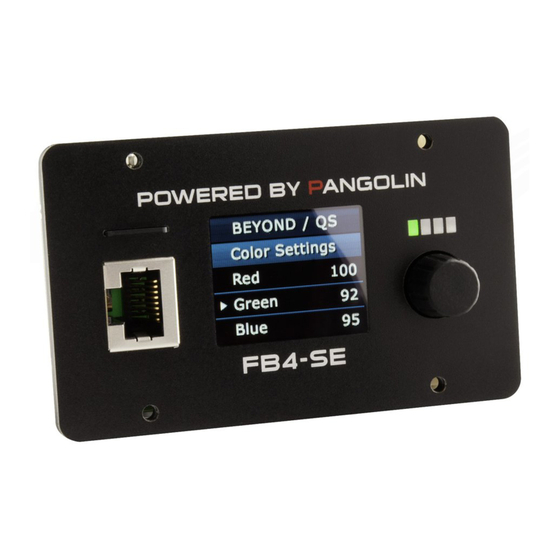
Pangolin FB4 SE Manual
Hide thumbs
Also See for FB4 SE:
- Quick start manual (11 pages) ,
- Quick start manual (9 pages) ,
- Manual (22 pages)
Table of Contents
Advertisement
The FB4 SE Manual
How to read this manual
• Thank you for purchasing this product by Pangolin Laser Systems.
Be sure to read this manual and operating instructions to get the most out of your
product.
• This manual consists mainly of explanations of hardware functionality. For detailed
instructions on operation QuickShow or BEYOND, see the corresponding software
manuals on http://pangolin.com.
• In this manual, menu option of the FB4 are enclosed in square brackets ([ ]) (e.g. Set
[Operation Mode] to [BEYOND/QS], Change [Artnet Settings] >> [Timeout] to 3.0).
Copyright: Pangolin Laser Systems Inc.
Advertisement
Table of Contents

Subscribe to Our Youtube Channel
Related Manuals for Pangolin FB4 SE


Summary of Contents for Pangolin FB4 SE
- Page 1 The FB4 SE Manual How to read this manual • Thank you for purchasing this product by Pangolin Laser Systems. Be sure to read this manual and operating instructions to get the most out of your product. • This manual consists mainly of explanations of hardware functionality. For detailed instructions on operation QuickShow or BEYOND, see the corresponding software manuals on http://pangolin.com.
-
Page 2: Table Of Contents
X-Y Scanner Position (feedback input) connections Color Output connections Shutter Actuator Output connection Ethercon input DMX Daughterboard connection Onboard Serial port output for DMX ILDA Daughterboard connection Troubleshooting Engineering Drawings Ilda Daughterboard DMX Daughterboard FB4 SE manual Version 0.91 Beta... -
Page 3: Fb4 Features And Options
Rotary encoder for 1 hand operation Full Color OLED Display Stand Alone operation Controllable through DMX and Artnet Options ILDA daughterboard for ILDA in and through. DMX daughterboard for XLR in and through EtherCON daughterboard for network connection. FB4 SE manual Version 0.91 Beta... -
Page 4: Fb4 Operation Modes
Settings are stored / saved on the SD card. Settings are stored when performing a “clean" [exit menu] through the main menu or two seconds of inactivity after making a change. FB4 SE manual Version 0.91 Beta... -
Page 5: Beyond/Qs
[BEYOND/QS] In operation mode [BEYOND/QS], Pangolin’s QuickShow and BEYOND software platforms are able to connect to the FB4 and control these directly through an ethernet network. For more information how to setup the FB4 through QuickShow or BEYOND, see the corresponding software manuals on http://pangolin.com. -
Page 6: Dmx-512
“DMX fixture”. Laser frames can be stored on the SD card and playback can be controlled by DMX. Laser frames can be uploaded by Pangolin’s QuickShow or BEYOND its FB4 Export wizard through an ethernet connection. -
Page 7: Art-Net
During this operation mode, the following menu options will be available. [Artnet Settings] (See page 12) [Master settings] (See page 11) [Geo Correction] (See page 14) [Color Settings] (See page 14) [Scan Guard] (See page 14) [Network Setup] (See page 15) FB4 SE manual Version 0.91 Beta... -
Page 8: Autoplay
Date and time can be setup through the QuickShow or BEYOND FB4 Export utility. The battery type required for this purpose is “CR1220”. The battery can be installed by pointing the negative side of the battery towards the circuit board. FB4 SE manual Version 0.91 Beta... -
Page 9: Timecode
[Operation Mode] [Time Code Setup] (See page 13) [Master Settings] (See page 11) [Geo Correction] (See page 14) [Color Settings] (See page 14) [Scan Guard] (See page 14) [FB4 Device Info] (See page 15) FB4 SE manual Version 0.91 Beta... -
Page 10: Ilda Mode
Test frames will need to be prepared and uploaded through Pangolin’s QuickShow or BEYOND its FB4 Export Utility. During preparation of the test frames an ethernet cable is required. Once the test frames are located on the SD card of the FB4, there is no cable connection needed to activate [test mode]. -
Page 11: Fb4 Settings
Note: Changing sizing inside QuickShow or BEYOND, modifies the resolution of the output image. When using master size on FB4 (ether through the QuickShow or Beyond FB4 settings editor or on the back of the FB4) the image will always maintain the highest resolution. FB4 SE manual Version 0.91 Beta... -
Page 12: Art-Net Settings
This value should be adjusted so that output does not stop too early, when the DMX framerate is low, but still in a timely manner when the DMX source disappears. (the default value is 3.0) FB4 SE manual Version 0.91 Beta... -
Page 13: Timecode Settings
Determines the maximum brightness used during display of the test frames [Master size] Determines the X and Y size of the projection output. * *Changing this value also changes [master size] in menu [master settings] FB4 SE manual Version 0.91 Beta... -
Page 14: Geo Correction
Defines how slow a beam may move before it will trigger the scanguard system. [Dwell Time] Defines how long a beam may be on when the beam speed is below [Min. Velocity]. [Invert Y] Easily invert the area where the scan guard is active. FB4 SE manual Version 0.91 Beta... -
Page 15: Network Setup
The Exit menu allows you to close the menu, turning the display off again. This is also the moment that all settings and values are saved on the SD card. Especially handy when replacing an SD card. FB4 SE manual Version 0.91 Beta... -
Page 16: Fb4 Status Indicator Leds
No SD Card Solid on SD Card Present Network status (Yellow) Network is not detected Double pulse every second Obtaining IP Address Steady pulse IP Address Obtained Solid on Connected to QS or BEYOND FB4 SE manual Version 0.91 Beta... - Page 17 Note: During a firmware update of the FB4 all four indication leds will be fully on. Note: If all four LEDs are blinking together, the FB4 has no valid firmware loaded and there is no valid firmware on the SD card. FB4 SE manual Version 0.91 Beta...
-
Page 18: Fb4 Onboard Dmx Out
Note, if no additional DMX output is required, use mode “BEYOND FB4 stream” mode to enable DMX output through the serial port on the FB4 as shown in the image below. The 3.3Volt serial port connections can be found on page 31. FB4 SE manual Version 0.91 Beta... -
Page 19: How-To Calculate The Base Address
The base address for universe 3, DMX address 1, is 1025 The base address for universe 4, DMX address 1, is 1537 The base address for universe 2, DMX address 128, is (512 + 128 = 640) FB4 SE manual Version 0.91 Beta... -
Page 20: Fb4 Fixture Modes
225-255 30K 0-255 Cue release 0-31 Default 8 Bit 33-95 Hold 97-159 Loop 161-223 Next 225-255 Stop 0-255 Color Scroll 0-31 Original cue color 8 Bit 33-223 Color Scroll 225-255 White Reserved Reserved 8 Bit FB4 SE manual Version 0.91 Beta... -
Page 21: Channel
16** 0-255 Cue speed Cue speed 8 Bit (0 = Original, 1 – 255 = 1% till 255%) 0-255 Dimmer Defines the maximum brightness 8 Bit limited by setup mode (Range 0 till 100%) FB4 SE manual Version 0.91 Beta... - Page 22 Channel 2 till 12 can only be modified when channel one is in setup mode During setup the red light on the FB4 will blink. During playback mode, the red light will burn continuously. FB4 SE manual Version 0.91 Beta...
- Page 23 If a BPM based effects is exported at 100BPM, and you want to have a cue running on 128 BPM, change the speed to 128. Lowering the scan rate can impact the cue speed of the laser FB4 SE manual Version 0.91 Beta...
-
Page 24: Hardware Connections
Hardware connections Power Input: The power requirement is a single +5 to +30 volts DC, at 2 watt. This may be sourced from the same power supply that feeds the scanners or laser diode drivers. FB4 SE manual Version 0.91 Beta... -
Page 25: Axis (X And Y Scanner) Output Connections
Axis (X and Y scanner) Outputs Axis Output Signal name Voltage level Y Positive + -5V to +5V Y Negative - -5V to +5V X Negative - -5V to +5V X Positive + -5V to +5V FB4 SE manual Version 0.91 Beta... -
Page 26: X-Y Scanner Position (Feedback Input) Connections
X-Y Scanner Position (feedback input) Connector The FB4 can optionally monitor the X-Y scanner's position signals and provide additional safety-related functions. Feedback Signal name Voltage level -10 to +10 -10 to +10 -10 to +10 -10 to +10 FB4 SE manual Version 0.91 Beta... -
Page 27: Color Output Connections
Color 2 (Green) 0 to +5V Color 3 (Blue) 0 to +5V Color 4 (Deep Blue) 0 to +5V Color 5 (Yellow) 0 to +5V Color 6 (Cyan) 0 to +5V Shutter 0 to +5V FB4 SE manual Version 0.91 Beta... -
Page 28: Shutter Actuator Output Connection
FB4 has a built-in PWM output which may be connected directly to an actuator, for the purposes of implementing a redundant mechanical shutter. Shutter Actuator Output Signal name PWM Voltage Output As a shutter actuator, we recommend ScannerMAX. (Visit http://scannermax.com for more information) FB4 SE manual Version 0.91 Beta... -
Page 29: Ethercon Input
If the Onboard ethernet port is in use, the Ether-con cannot be used. Ethercon Input Signal Name Lan Earth Lan TX Positive Lan TX Negative Lan RX Positive Lan RX Negative reserved reserved reserved reserved FB4 SE manual Version 0.91 Beta... -
Page 30: Dmx Daughterboard Connection
The DMX of the FB4 is accessible through the FB4 menus. Signal name VCC (3.3V) I2C INT I2C SDA I2C SCL DMX TL DMX RX FB4 SE manual Version 0.91 Beta... -
Page 31: Onboard Serial Port Output For Dmx
The FB4 allows you to utilize the FB4’s onboard Serial port as DMX output for, for example gratings. More information on this subject on page 18. Signal name Voltage level Serial Port TX 3.3V TTL Serial Port RX 3.3V TTL FB4 SE manual Version 0.91 Beta... -
Page 32: Ilda Daughterboard Connection
NOTE: The FB4 ILDA board will not generate ILDA out in [BEYOND/QS] mode. The FB4 is meant as OEM device to be built in, into a laser or external housing. All wires will need to be connected to the corresponding ports on the FB4. FB4 SE manual Version 0.91 Beta... -
Page 33: Troubleshooting
Connect the scanners and diode drivers, directly to the FB4. (See pages 26-27) Problem: The output of the lasers is flickering in [DMX-512]/[Art-net] modes Resolution: Try to raise or lower the [DMX-512]/[Art-net] [timeout] settings. (see page 12) FB4 SE manual Version 0.91 Beta... -
Page 34: Engineering Drawings
FB4 SE manual Version 0.91 Beta... -
Page 35: Ilda Daughterboard
FB4 SE manual Version 0.91 Beta... -
Page 36: Dmx Daughterboard
FB4 SE manual Version 0.91 Beta...
Need help?
Do you have a question about the FB4 SE and is the answer not in the manual?
Questions and answers