Advertisement
Quick Links
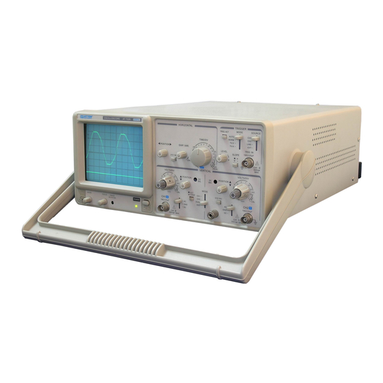
Instruction Manual for
AT7328/7340 Dual Channel Oscilloscope
Introduction
1. AT7328 /7340 Series Dual Channel Oscilloscope, Maximum sensibility is 5mV/div, maximum sweep speed is
0.2 s/div, and can be expanded ten times to 20ns/div. This item apply 6in with red graticule rectangular CRT, with
stable and reliable performance.
2. Feature
CRT with Bright and high accelerated pole voltage
This oscilloscope tube is of fast speed and high light. Voltage of accelerated pole up to 2kV, it can be able to
display clear traces even under high-speed sweep.
The alternative triggering function can observe different signal waveform in two frequencies.
TV signal synchronous function
CH1 output
50 output signal in the rear panel can drive frequency counter directly or other instrument.
Z-axial input
Function of bright adjustable can add frequency or time marker to oscilloscope, trace of positive signal
blanking, TTL matching
X-Y operation
This item can be used as an X-Y oscilloscope while setting in X-Y position, CH1 is horizontal axial and CH2 is
vertical axial.
Advertisement

Related Manuals for Atten AT7328 Series


Summary of Contents for Atten AT7328 Series
- Page 1 Instruction Manual for AT7328/7340 Dual Channel Oscilloscope Introduction 1. AT7328 /7340 Series Dual Channel Oscilloscope, Maximum sensibility is 5mV/div, maximum sweep speed is 0.2 s/div, and can be expanded ten times to 20ns/div. This item apply 6in with red graticule rectangular CRT, with stable and reliable performance.
- Page 2 ATTEN Electric Instrument Series 1. Spectrum analyzer Frequency Expander 2. Sweeping Graph Show Spectrum Analyzer 3. EMC Pre-Authentication Measurement 1) Electric Network Conduction ,Radiated Interference Test Interface 2) Spectrum Analyzer Probe 4. Signal Generator 5. Frequency Counter / Power Meter 6.
-
Page 3: Specifications
Specifications Item 20MHz Oscilloscope 40MHz Oscilloscope Data AT7328 AT7340 Sensitivity 5mV 5v/div Accuracy Trimming Sensitivity 1/2.5 or less than panel graduation DC 20MHz Frequency Bandwidth AC Coupling: 10Hz Rise Time Approx.17.5 ns Approx. 17.5 ns Input Impedance 1M /25PF Waveform Characteristic 5%(in 10mv/DIV range) Other Distortion : Add 5% to this Value DC Balance Shift... - Page 4 Polarity 20Hz—2MHz : 0.5DIV TRIG.-ALT : 2DIV EXT : 200Mv 2—20MHz : 1.5DIV 2---40MHz : 1.5DIV TV : Synchronous pulse > 1 DIV(EXT : 1V) AUTO : When no trigger signal input , sweep is under free mode.(apply to above 25Hz repeated signal) NORM : When no trigger signal , track is under armed state but no display Trigger mode...
- Page 5 Type 6 in, Rectangle, Inside graduation Phosphor Acceleration Voltage Approx 2kV 200MHz CRT Screen Size 8×10DIV[1DIV=10mm(0.39in)] Graduation Inside Trace rotation Adjustable via panel Power requirement: Operating Ambient: Accessories: • Voltage: Fixed AC220v±10% or • Power cord: ×1 Indoor, 2000m elevation •...
- Page 6 Make sure there is no other article in the sink hole of oscilloscope. 5. CRT magneto-optical coating Do not set the CRT trace in a extremely bright position or focus the bright spot stay for a long period of time. 6.
- Page 7 10) 18) – AC-GND-DC: Choose input mode of input signal of vertical axial AC: AC coupling GND: input grounding of vertical amplifier, input switch off DC: DC coupling Vertical attenuation switch: adjust vertical reflection sensibility vary from 5mV/div 5V/div, in 10 steps 9) 21) Vertical fine-tune: Fine-tune sensibility not less than 1/2.5 of nominal;...
-
Page 8: Operation Methods
(Synchronizing TV-Vertical and TV-Horizontal only in the case of synchronous signals are negative pulses) Time base Horizontal sweep speed switch: Sweep speed is divided into 20 steps, from 0.2 S/div to 0.5S/div. And set X-Y position can use as X-Y oscilloscope. Horizontal fine tune: Fine tuning the time of horizontal sweep, in order to calibrate the sweep time in accordance with TIME/DIV on panel. - Page 9 switches and control knobs. Adjust intensive and focus respectively, make the traces clear. Adjust CH1 position knob and trace turning potentiometer to parallel the trace and horizontal scale (use screw driver to adjust trace turning potentiometer 4). Input the calibrated signal to CH1 input port by using 10:1 probe. Set the switch AC-GND-DC in AC state.
- Page 10 oscilloscope must be negative. (See fig 5) Function of trigger source: In order to display a stable waveform on screen, a signal which is relate with display signal in time should be provided to trigger circuit, the trigger switch is just used to select the trigger signal. CH1/CH2: Internal trigger mode in most cases.
- Page 11 can observe the waveform of the whole area. 17 NI 9. X-Y operation Set the sweep rate switch in X-Y position, the mode of oscilloscope is X-Y. X-axial: CH1 input Y-axial: CH2 input Y-EH EH Y-axial X-EH X-axial Note: when HF signal in X-Y mode, should notice the difference of frequency and phase of X and Y axial £...
- Page 12 1 ˜X ¯Eg 9 CH1 (X) input >D £ Attenuation Pre-amplify E F’ 1 Eg ˛ CH1 (X) output E F’ 1 ?” ¥ “ CH1 trigger sampling V,¨ ? £ Vertical sweep switch V,¨Eg ˛ ß Vertical output amplify E F’...
Need help?
Do you have a question about the AT7328 Series and is the answer not in the manual?
Questions and answers