
Related Manuals for Axis Industries QALCOSONIC HEAT 2


Summary of Contents for Axis Industries QALCOSONIC HEAT 2
- Page 1 A B “AXIS INDUSTRIES” ULTRASONIC HEAT METER QALCOSONIC HEAT 2 TECHNICAL DESCRIPTION, INSTALLATION AND USER INSTRUCTIONS PESHEAT2V01 KAUNAS...
- Page 2 SAFETY REQUIREMENTS Before operating the meter, please read this technical description and user's manual thoroughly and follow their instructions. When the meter is powered from the battery (3.6 V), risk factors during the meter installation and service is a heat conveying fluid with inner pressure up to 2,5MPa and temperature up to ...
-
Page 3: Table Of Contents
Annex E. Outline and mounting dimensions of ultrasonic flow sensors………....... Annex F. Outline and mounting dimensions of temperature sensors........EC DECLARATION OF CONFORMITY AB Axis Industries herewith declares, that this product complies with the relevant requirements of the following directives: - 2014/32/EU... -
Page 4: Application Field
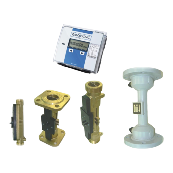
Heat meter QALCOSONIC HEAT 2 consists of the primary flow sensor and the calculator with type approved pair of temperature sensors with Pt500 elements. - Page 5 Essential requirements - Annex MI-004 Heat meter , QALCOSONIC HEAT 2 complies with the European standard EN 1434 “Heat meters”. QALCOSONIC HEAT 2fulfils “C” class environment protection requirements according to EN1434-1:2007 Climatic ambient temperature range: from 5 ° to 55 ° C...
- Page 6 Type number combination of the heat meter QALCOSONIC HEAT 2 for order placing: – □□ – □ – □□ – □ – □□ – □□ – □□ – □□ – □ QALCOSONIC HEAT 2 Type Measurement scheme: Conventional Code Conventional...
- Page 7 Table 1.2 Codes of flow sensors Permanent flow rate q Overall length, mm End connections Code G ¾ DN20 G ¾ DN20 G ¾ G ¾ DN20 DN20 G1 ¼ DN25 DN32 G1 ¼ DN25 DN32 10,0 10,0 DN40 15,0 DN50 25,0 DN65...
-
Page 8: Technical Data
2. TECHNICAL DATA 2.1. Energy measurement 2.1.1. Accuracy class - 2 Maximum permissible heat energy measurement error of calculator and flow sensor: Maximum permissible heat energy measurement error of complete meter (error of temperature sensors pair included): E = (3+4 ... - Page 9 - Resolution of indication of temperatures and temperature difference 5,5 mkA - Maximum permissible RMS value of sensor current Θ >181 - Recorded errors and their duration C (or open circuit), Θ < -41 C (or short-circuit). NOTES: - additional 3rd channel selects the user during on-site installation ** - selected by the customer when ordering the device *** - depending on the value of the lower measurement limit of the temperature difference of the connected pair of temperature sensors...
- Page 10 Temperature limits of heat conveying liquid: Θ = 5..130 ºC (to all measurement schemes, except U1L and U2L); Θ = 0..130 ºC (to measurement schemes U1L and U2L, intended for the account of energy for heating and cooling); Accuracy class Limits of a permissible error of volume (mass) measurement: = ...
- Page 11 Table 2.2 Maximum Minimal permissible Power supply of meter/ Connection permissible pulse pulse or pause Flow pulse input type cable length , m frequency, Hz duration, ms Mains supply / Active or passive pulses <100 m 200 (5) 2,5 (100) (transistor key or mechanical contact) Battery supply/ Passive pulses...
- Page 12 Display resolution (directly corresponding with pulse output value), depending on programmed maximum flow rate value (the highest value of the flow channel, involved in the energy calculation formula), is provided in the Table 2.3 Table 2.3 Displayed fluid volume (mass) lowest Displayed energy lowest digit value Maximum flow digit value (flow pulse output value),...
- Page 13 2.8. Data recording and storage Following daily, weekly and monthly parameter values are recorded in heat meter memory: - absolute integral instantaneous parameter values (listed in Table 2.4) - hourly, weekly and monthly alterations of integral parameters - hourly, weekly and monthly average values for all measured temperature and pressure values - error (fault) and information codes (see paragraph.
- Page 14 The configurable pulse-frequency output in “pulse mode” can be used for thermal energy (E, E1, E2, E3) or quantity of liquid V1 (M1), V2(M2), V3(M3), V4 pulses Pulse value will correspond to the lowest digit of indicated parameter. The configurable pulse-frequency output in “frequency mode” or current output can be used for thermal power , flow rate (q1, q2, q3, q4), temperature (1, 2, 3) or pressure (p1, p2) pulses.
- Page 15 , Mains supply AC (502) Hz, 230 V Power supply < 3 VA (only for meter) - Consumption of energy per year up to 26.3 kWh; Power supply < 15 VA (for meter and extra sensors) Consumption of energy per year up to 131,5 kWh;...
-
Page 16: Accessories And Sub-Assemblies
(listed in Table 3.1): Table 3.1 Item Amount, 1. Heat meter calculator QALCOSONIC HEAT 2 2. Technical description, user manual for heat meter QALCOSONIC HEAT 2 3. Mounting kit for heat meter calculator 1…2* 4. Ultrasonic flow sensors 5. Internal baterry 3,6 V 6. -
Page 17: Operating Principle
4. OPERATING PRINCIPLE Ultrasonic heat and water meters QALCOSONIC HEAT 2 is multichannel programmable microprocessor measuring device which consists of electronic unit (calculator) and the initial flow (up to 2), temperature (up to 3) and pressure (up to 2) sensors.. -
Page 18: Safety Requirements
Mounting seal: -one or two hanged seals on the fixers of junction of the top and botton part of the calculator (Annex D) -seals on the protective cover and mounting bolt of temperature sensors (see Annex F, Fig.1...2). 6. SAFETY REQUIREMENTS When the meter is powered from the battery (3.6 V), risk factors during the meter installation and service is a heat conveying fluid flowing within flow sensor with inner pressure up to 1,6 MPa and temperature up to 180... - Page 19 For flow sensors of the heat meter with nominal diameter DN65….DN100 necessary straight pipelines lengths are: upstream ≥ 5 × DN, downstream ≥ 3 × DN. For flow sensors of other sizes the straight pipelines installation in upstream and downstream the sensor are not necessary. Avoid the flow sensor installation near after the pumps which can cause cavitations.
- Page 20 When configuration (programming) mode is active, label “SET” is displayed in the upper right conner of the display. All parameters have to be programmed. The algorithm for setting up parameters, possible parameter limits and abbreviations are listed in Table 7.1. Table 7.1 Menu description LC Display example...
- Page 21 1…12, “- -“(month number from 1 to 12); Month number and to it 0…99,9 corresponding established value of For example: 12 month, 4 20,0 cold water temperature constant4 (when „--„ - value 4 is valid for all months) 0…150 Auxiliary constant of temperature 5.Is used for verification in (In verification mode value of 5 is set to "TEST"...
- Page 22 (0,0…25000) kPa Maximum rated value of pressure sensors, kPa (0,0…9999,9) kPa The pressure value used in calculations of heat *, kPa If specify "0.0 kPa" - for calculation is used the measured pressure value (p1 – for flow pipe , p2–for return pire) MWh (kWh), Gcal ar GJ Thermal energy units * Measurement units of quantity of a...
- Page 23 Keeping the accuracy of preset flow temperature (hysteresis), (only for mode On2) the maximum allowed value of flow temperature ( threshold value protection), C (only for mode On2) Software version number* LCD segment test* Notes: The displayed parameters list can be shorter depending on the selected modification, and a meter configuration (parameters, inappropriate for the given configuration will not be shown).
- Page 24 7.2.2. Parameterization (configuration) procedure Recommendations for the configuration change Measurement circuits, energy calculation algorithms, type of the temperature sensors, value of pressure for thermal energy calculation and numbers of flow sensors should be checked according to individual heat meter data (see Paragraph 13). If are required by measurement circuit, other parametres of a configuration should be made active and entered: The additional flow inputs (V3 and V4) are activated, the inputs parameters values corresponding...
- Page 25 required current limits of the 1-st and 2-nd current outputs are set by switching the jumpers “I1” and “I2” into one of the following positions: “4-20 mA” or “0-20 mA”. required type of pulses output are set by switching the jumpers „+P1 +P2 GND“: Galvanically isolated passive pulses outputs - not jumpers Galvanically isolated active (+24 V) pulses- „GND“, “+P1”...
-
Page 26: Operation
(calculating unit, flow, pressure and temperature sensors) is installed correctly. If measured parameter values are not displayed correctly, it is necessary to verify the installation. 8. OPERATION 8.1. Control buttons The information can be displayed using two control buttons which are on the top of the calculator(see Fig. - Page 27 Key to symbols Description 1. Groups of parameters Group of displaying corresponding parameters (display level) 2. Number and group of indicated parameters 1…5 Number of energy tariff or number of measurement channel (volume, flow, temperature, pressure) Differences (difference of heating medium quantity (M1-M2), (V1-V2) or temperature difference (1-2) 3.
- Page 28 Press and hold ( 3 s) button or button to move to the next display level. To view data in the same display level press shortly ( 3 s) buttons . The display will switch automatically to the highest level of displaying current values of integral parameters, or – if at least one error has been detected –...
- Page 29 Accumulated volume V1 or mass M1 Accumulated volume V2 or mass M2 Reverse flow fluid volume (mass) for 2-nd channel (winter/summer operation mode only) Accumulated volume V3 or mass M3 Accumulated volume V4 Differences of volume (V1—V2) or mass (M1-M2) Vandens kiekių...
- Page 30 Significant faults Er If significant faults Er are detected in work of heating system, energy calculation is stopping and these errors are displayed via 6 character error code: Status of temperature sensor T1 Status of temperature sensor T2 Status of temperature sensor T3 Status of flow sensor V1 Status of flow sensor V2 Power supply voltage status (only for archive)
- Page 31 Transistory fault Er If transistory faults Er are detected in work of heating system, energy calculation do not stop and these errors are displayed via 5 character error code: Status of flow sensor V1 Status of flow sensor V2 Status of flow sensor V3 Status of flow sensor V4 Status of temperature sensor Detailed description of transistory faults codes Er...
- Page 32 8.2.3. Displaying (viewing) instantaneous (informative) parameters values (level 2) Parameter values are displayed in sequence, shortly pressing buttons: - next parameter, previous parameter Thermal power Flow rate q1. Negative flow rate is marked with minus (-) in the display (measurement units - m3/h or t/h) Flow rate q2.
- Page 33 By shortly pressing button you can select parameter value for viewing. By shortly pressing button you can select for viewing previous set day parameters values (previous months or previous years data depends on configuration of calculator) To display archive data (see p.8.2.4.2) press and hold button If a set day function is inactive - archive data review mode (p.8.2.4.2) will be displayed immediately when you enter to level „LOG“.
- Page 34 Table 8 Symbol on the upper Measurement unit Parameter Parameter value part of display (parameter symbol) code Zone B (Zone C) Zone E Zone A Σ MWh (Gcal, GJ) Total thermal energy E MWh (Gcal, GJ) Thermal energy component E1 MWh (Gcal, GJ) Thermal energy component E3 t (m3)
- Page 35 Fig. 8.3. Conection of printer via optical interface several times, until label “PRN” is To enter report printing mode, press and hold button reached. LCD will display the following: Time interval System number Report type Select blinking LCD zone (report type, time interval or heating system number) by shortly pressing button .
- Page 36 Holding down button stores the selection, and report ending date selection mode will be activated. LCD displays (h mm.dd ) : Report ending date and time is defined in the same way as describe above. Printing will start after holding down button one more time.
- Page 37 8.3.2. Programming relay output parameters in regulation mode On1 At work in this mode the regulator can maintain temperature in the established limits, forbid value of temperature to exceed an admissible maximum limit, forbid value of temperature to fall below an admissible minimum limit or to form alarm signal at occurrence of such disturbances.
-
Page 38: Verification
Waranty period - 12 months from bringing into operation, but not more than 18 months from manufacturing date. Manufacturer’s address: AB “Axis Industries ”, Kulautuvos g. 45a, Kaunas LT-47190, Lithuania tel. +370 37 360234; fax. +370 37 360358. PESHEAT2V01 2016-01-08... -
Page 39: Individual Technical Data
12. INDIVIDUAL DATA Serial number of meter Code of type of measurement circuit Accuracy class Temperature difference measurement range Flow sensors data: Serial number Maximum flow rate q Permanent flow rate q Minimum flow rate q Nominal pressure PN, MPa Connection type Overall length, mm Temperature sensors type... -
Page 40: Annex A. Measurement Schemes And Energy Calculation Formulas
Annex A Measurement schemes and energy calculation formulas Application type Energy calculation formula For closed heating/cooling systems U1 - Meter for heating. Flow sensor in flow pipe (h E=V1 M1 =V1 (h U2 - Meter for heating. Flow sensor in return pipe E=V1... - Page 41 Annex A Application type Energy calculation formula For closed heating/cooling systems U1L – Meter for heating and cooling. ∑E = E1 + E2 The flow sensor in flow pipe kai Θ1 > Θ2: (h E1=V1 ), E2=0 kai Θ1< Θ2: (h E2=V1...
- Page 42 Annex A Application type Energy calculation formula For closed or opens heating systems A1 – For closed heating system with flow sensor in ∑E = E1 + E2 * return pipe or for open heating system for accounting (h energy consumption for heating and hot water E1=V2...
- Page 43 Annex A Application type Energy calculation formula For combined heating - hot-water preparing systems ∑E = E1 + E2 * U1A3- Two independent heat meters: 1st - For closed heating system with flow sensor in (h flow pipe. E1=V1 2nd -For accounting of hot water energy* (h E2= V2...
-
Page 44: Annex B. Electrical Wiring Diagrams
Annex B Electrical wiring diagrams Fig. B1. Electrical wiring diagram Temperature sensors with 4-wire (K) connection T1 … T3 - temperature sensors V1 … V2 - ultrasonic flow sensors V3... V4 – water meters with pulse output p1 ... p2 -pressure sensors Remark: 1. - Page 45 Annex B Electrical wiring diagrams Fig. B2. Electrical wiring diagram Temperature sensors with 2-wire (D) connection T1 … T3 - temperature sensors V1 … V2 - ultrasonic flow sensors V3... V4 – water meters with pulse output p1 ... p2 -pressure sensors Remark: 1.
- Page 46 Annex B Electrical wiring diagrams Fig. B3. Wiring diagrams for connecting of the meter to the line voltage 230 V and for connecting of the regulating valve. Valve power supply and meter supply is 230 V Fig. B4. Direct connection of the meter to the computer interface RS-232 Fig.
- Page 47 Annex C Table C1. Numbering of terminals Terminal Signal description Marking number V1-1 ( +) Output signal (OUT) from 1st flow sensor V1 (ultrasonic sensor 1) V1-1( -) GND for output (OUT) of 1st flow sensor V1 (ultrasonic sensor 1) V1-2 (+ ) Input signal (IN) from1st flow sensor V1 (ultrasonic sensor 2) V1-2 ( - ) GND for input (IN) of 1st flow sensor V1 (ultrasonic sensor 2) V2-1 (+ ) Output signal (OUT) from 2nd flow sensor V2 (ultrasonic sensor 1)
- Page 48 Annex C Table C2. Numbering of additional module terminals Terminal Signal description Marking number Numbering of power supply module terminals ˇ Relay output “decrease” GND for relay output ˆ Relay output “increase” ╧ Main ground 230V Mains power supply (230V AC) 230V Mains power supply (230V AC) Numbering of communication module terminals...
- Page 49 Annex D Fig.D1. Mounting dimensions of calculator PESHEAT2V01 2016-01-08...
- Page 50 D1.1. Adapter plate according to figure 8 of EN1434-2:2007 for wall mounting of calculator It can be used for wall mounting, if the aperture in the wall is too large for the calculator 1 – calculator QALCOSONIC HEAT 2 2 – adapter plate 3 –...
- Page 51 Fig. D3. Wall mounting, with possibility sealing of mounting Fig.D4. Mounting on standard DIN-rail Fig.D5. Panel mounting PESHEAT2V01 2016-01-08...
- Page 52 Annex D a) G 1 ¼ (qp = 3,5 m3/h; qp = 6,0 m3/h ) b) G 2 (qp = 10,0 m3/h) c) DN 50 (qp = 15,0 m3/h) Fig. D6. Mounting on ultrasonic flow sensor Flow temperature max. 90 PESHEAT2V01 2016-01-08...
- Page 53 Annex E Sizes and dimensions of ultrasonic flow sensors Fig. E1. Dimensions of flow sensors G3/4“ , L=110 mm or 165mm Fig. E2. Dimensions of flow sensors G1“ , L=130 mm or 165mm PESHEAT2V01 2016-01-08...
-
Page 54: Dn25
Annex E Fig. E3. Dimensions of flow sensors DN20 , L=190 mm Fig. E4. Dimensions of flow sensors G1 1/4“ , L=260 mm PESHEAT2V01 2016-01-08... - Page 55 Annex E Fig. E5. Dimensions of flow sensors DN25 , L=260 mm Fig. E6. Dimensions of flow sensors G2“ , L=300 mm PESHEAT2V01 2016-01-08...
-
Page 56: Dn40
Annex E Fig. E7. Dimensions of flow sensors DN40, L=300 mm (two design options) PESHEAT2V01 2016-01-08... -
Page 57: Dn50
Annex E Fig. E8. Dimensions of flow sensors (Brass housing) DN50, DN65, DN80, DN100 DN65/PN16 DN65/PN25 DN80 DN100 Fig. E9. Dimensions of flow sensors (Steel housing) DN65, DN80, DN100 PESHEAT2V01 2016-01-08... -
Page 58: Dn65
Annex E Security sealing a) Flow sensor G 3/4“ b) Flow sensor G 1“ or DN20 c) Flow sensor G 1 ¾“ or DN25 d) Flow sensor G 2“ or DN40 e) Flow sensor DN50, DN65, DN80, DN100 f) Flow sensor DN65, DN80, DN100 (Brass housing) (Steel housing) Fig.E10. - Page 59 Annex F Installation recomendation and sealing of temperature sensors Seal Seal Boss Pocket a)Without pocket b) With pocket Fig.F1. Installation recomendations for temperature sensors with mounting head Seal Seal Pocket Boss a) angled 45 b) perpendicular Fig.F2. Installation recomendations for temperature sensors with permanently connected signal leads PESHEAT2V01 2016-01-08...
-
Page 60: Dn100
Annex F a) Temperature sensors with permanently connected signal leads L- signal leads length Nominal daimeter of pipe, mm DN20...DN100 DN125...DN150 Total length of pocketL, mm b) Temperature sensors pocket Fig.F3. Dimensions of temperature sensors type PL-6 and theirs pockets via a tee using a valve-tee Fig.F4.
Need help?
Do you have a question about the QALCOSONIC HEAT 2 and is the answer not in the manual?
Questions and answers