Table of Contents
Advertisement
Quick Links
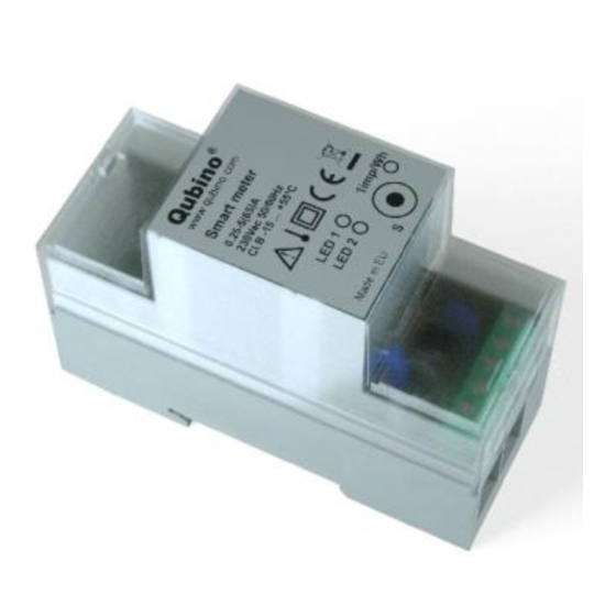
Qubino
The INNOVATIVE and SMALLEST
Smart meter
ORDERING CODE
Z-WAVE FREQUENCY
ZMNHTD1
868,4 MHz
ZMNHTD2
921,4 MHz
ZMNHTD3
908,4 MHz
ZMNHTD4
869,0 MHz
ZMNHTD5
916,0 MHz
This
Z-Wave module is
used for energy
measurements in single-phase electrical power
network and can be used in residential, industrial
and utility applications. Meters measure energy
directly in 2-wire networks according to the
principle of fast sampling of voltage and current
signals. A built-in microprocessor calculates
energy, power and power factor from the
measured signals.
The module can be controlled through Z-wave
network and it acts as repeater in order to
improve range and stability of Z-wave network.
It is designed to be mounted on DIN rail.
Installation
Before the installation disconnect power
supply.
Connect the module according to electrical
diagram.
Locate the antenna far from metal elements
(as far as possible).
Do not shorten the antenna.
Danger of electrocution!
Module installation requires a great degree
of skill and may be performed only by a
qualified and licensed electrician.
Even when the module is turned off, voltage
may be present on its terminals. Any works
on
configuration
changes
related
to
connection mode or load must be always
performed by disconnected power supply
(disable the fuse).
Note!
Do not connect the module to loads exceeding
recommended values. Connect the module only
in accordance to the below diagrams. Improper
connections
may
be
dangerous.
It
is
recommended to use 65 A fuses for the line
protection.
Package contents
Smart meter
Electrical diagram 230VAC
IR
IR
Notes for the diagram:
LI
Live input
NI
Neutral input
Lo
Live output
No
Neutral output
1
Input for IR external relay/Ext. relay
2
Neutral lead for input
4
Live lead for External relay output
5
Output for External relay (max. 3W)
S
Service button (used to add or
remove module from the Z-Wave
network).
LED1
Green - Power on (solid) / no ID
(blinking slow 1s) / Inc./Exc. mode
(blinking fast 0,5s)
Yellow on – output on (any) /
LED2
Yellow off – outputs off (both)
IR
Output for IR external relay
1imp/
Red - Pulse rate
Wh
Measurements
Voltage
V
Current
I
Power – Active
W
Power – Active total
kWh
Power – Reactive
var
Power – Reactive total
kvarh
Power – Apparent total
kVAh
Power Factor
PF
External relays
It is possible to connect two external relay to
Smart meter module. One controlled by built-in
optical (IR) communication port on the side,
second controlled by output on terminal 5.
Module Inclusion (Adding to Z-wave
network)
Connect module to power supply
enable add/remove mode on main controller
auto-inclusion (works for about 5 seconds
after connected to power supply) or
press service button S for more than 2
second
NOTE: For auto-inclusion procedure, first set
main controller into inclusion mode and then
connect module to power supply.
Module
Exclusion/Reset
(Removing
from Z-Wave network)
Connect module to power supply
bring module within maximum 1 meter (3 feet)
of the main controller,
enable add/remove mode on main controller
press service button S for more than 6
seconds.
By this function all parameters of the module are
set to default values and own ID is deleted.
If service button S is pressed more than 2 and
less than 6 seconds module is excluded, but
configuration parameters are not set to default
values.
Association
Association enables Smart meter module to
transfer commands
inside
Z-Wave network
directly to other Z-Wave modules.
Associated Groups:
Group
1:
Lifeline
group
(reserved
for
communication with the main controller), 1 node
allowed.
Configuration parameters
Parameter no. 7 – Input 1 switch function
selection
Available configuration parameters (data type is 1
Byte DEC):
default value 4
0 disabled
2 IR external relay control – mono stable
push button
3 IR external relay control - bi stable switch
4 External relay control – mono stable push
button
5 External relay control – bi stable switch
Parameter no. 10 - Activate / deactivate
functions ALL ON / ALL OFF
Available configuration parameters (data type is 2
Byte DEC):
default value 255
255 - ALL ON active, ALL OFF active.
0 - ALL ON is not active, ALL OFF is not
active
1 - ALL ON is not active, ALL OFF active
2 - ALL ON active, ALL OFF is not active
Smart meter module responds to commands ALL
ON/ ALL OFF that may be sent by the main
controller or by other controller belonging to the
system
Parameter no. 11 - Automatic turning off IR
external relay output after set time
When
IR
external
relay
is
ON
it
goes
automatically OFF after time defined by this
parameter. Timer is reset to zero each time the
module receive ON command regardless from
where it comes (push button, associated module,
controller,..). Available configuration parameters
(data type is 2 Byte DEC):
default value 0
0 = Auto OFF disabled
1 – 32535 = 1second – 32535 seconds. Auto
OFF enabled with define time, step is 1s.
Parameter no. 12 - Automatic turning on IR
external relay output after set time
When IR
external
relay
is
OFF
it
goes
automatically ON after time defined by this
parameter. Timer is reset to zero each time the
module receive OFF command regardless from
where it comes (push button, associated module,
controller,..). Available configuration parameters
(data type is 2 Byte DEC):
default value 0
0 = Auto ON disabled
1 – 32535 = 1second – 32535 seconds. Auto
ON enabled with define time, step is 1s.
Parameter no. 13 - Automatic turning off
External relay output after set time
When External relay is ON it goes automatically
OFF after time defined by this parameter. Timer
is reset to zero each time the module receive ON
command regardless from where it comes (push
button,
associated
module,
controller,..).
Available configuration parameters (data type is 2
Byte DEC):
default value 0
0 = Auto OFF disabled
1 – 32535 = 1second – 32535 seconds. Auto
OFF enabled with define time, step is 1s.
Parameter no. 14 - Automatic turning on
External relay after output set time
When External relay is OFF it goes automatically
ON after time defined by this parameter. Timer is
reset to zero each time the module receive OFF
command regardless from where it comes (push
button,
associated
module,
controller,..).
Available configuration parameters (data type is 2
Byte DEC):
default value 0
0 = Auto ON disabled
1 – 32535 = 1second – 32535 seconds. Auto
ON enabled with define time, step is 1s.
Parameter no. 40 – Power reporting in Watts
on power change
Set value means percentage, set value from 0 –
100 = 0% - 100%. Available configuration
parameters (data type is 1 Byte DEC):
default value 10
0 = Reporting disabled
1 – 100 = 1% - 100% Reporting enabled.
Power report is send (push) only when actual
power in Watts in real time changes for more
than set percentage comparing to previous
actual power in Watts, step is 1%.
NOTE: if power changed is less than 1W, the
report is not send (pushed), independent of
percentage set. When reporting Watts, module
will automatically reports also V (Voltage), A
Advertisement
Table of Contents

Related Manuals for QUBINO Smart meter


Summary of Contents for QUBINO Smart meter
- Page 1 ON ZMNHTD3 908,4 MHz It is possible to connect two external relay to Byte DEC): command regardless from where it comes (push Smart meter module. One controlled by built-in ZMNHTD4 869,0 MHz default value 4 button,...
- Page 2 3 = Endpoints IR external relay and External Starting current: 20 mA EC Directive on Low Voltage 2006/95/EC Command Classes: Qubino 230 V (±20 %) relay enabled Voltage (Un): EC Directive WEEE 2002/96/EC COMMAND_CLASS_ZWAVEPLUS_INFO_V2 NOTE: After parameter change module has to be Power consumption at Un: <...
Need help?
Do you have a question about the Smart meter and is the answer not in the manual?
Questions and answers