
Subscribe to Our Youtube Channel
Related Manuals for Videocon Shine


Summary of Contents for Videocon Shine
- Page 1 Model : Shine (WM VSH60LMC, WM VSH60PMC, WM VSH60EMC, WM VSH60AMC) Model : Star (WM VST60LMW)
-
Page 2: Table Of Contents
SAFETY PRECAUTION ! DISASSEMBLE POWER CORD BEFORE SERVICING RECONNECT ALL GROUNDING DEVICES IMPORTANT SAFETY NOTICE ! This service information is intended for individuals possessing adequate background of electrical, electronic and mechanical experience. Any attempt to repair this appliance may result in personal injury or property damage. -
Page 3: Specification
1. SPECIFICATIONS Shine Star MODEL : Power Supply 240V, 50 Hz AC 240V, 50 Hz AC Washing Capacity 6.0 Kg 6.0 Kg Max. 60 Liters* Max. 60 Liters* Water Level Min. 30 Liters Min. 30 Liters Rated Power Wash : 340 Watts... -
Page 4: Precaution
2. PRECAUTION When performing troubleshooting and part replacement during servicing, note the following safety precautions: 1-1.Safety Precautions 1-1-1.Use Genuine Parts The components of the washing machine have safety features such as non-combustibility and voltage withstanding.Therefore, always use the same part as suggested by the maker. In particular, be sure to use only design rated parts in case of major safety parts identified by the marker. -
Page 5: Cautions For Safety
3. CAUTIONS FOR SAFETY Please observe the following notes for safety. The symbols indicate as follows. Symbol Meaning Indicates possibility of death or serious injury of a repair technician and a WARNING person near by through them is conducted work, or of a user by a defect of the product after the work performed by the technician. - Page 6 3. CAUTIONS FOR SAFETY WARNING After repair, measure insulation resistance between the charging part (power cord plug) and the non-charging metallic part (ground) with an insulation resistance meter(500V).The resistance shall be10M Ohm or more. Failing to check the insulation resistance may cause a short circuit, electric CHECKINSULA- shock or other diseases to the customer.
- Page 7 3.CAUTIONS FOR SAFETY CAUTION Ask an service enginer to install the product. Install the product securely and safely according to the electrical equipment technical standard and the wiring standard. INSTALL Incorrect work causes an electric shock and a fire. CAREFULLY Do not pull the power cordwhen unplugging.
-
Page 8: Installation Instructions
4. INSTALLATION INSTRUCTION 4-1.Installation 15cm 4-1.Level Specifications and Wall-Clearance Distances 15cm 1) Instal the washing machine on a solid and level floor. 2) Place menton an inclined, weak or rough floor may cause abnormal noise or trembling. 3) Place the machine at least 15cm away from the wall. 4-2. - Page 9 4. INSTALLATION INSTRUCTION 4-5. Positioning the Drain Hose 1)When there is no threshold, the length of the drain hose should not exceed 3m. 2)When it is necessary to connect the drain hose with the drain outlet far away, connect the extension hose and applicable parts available from...
-
Page 10: Operating Instructions
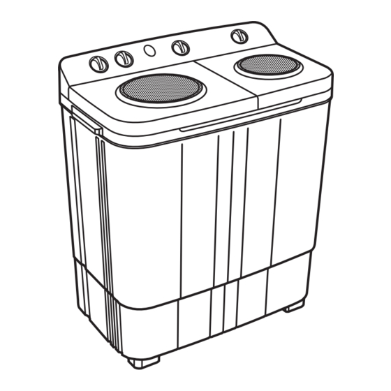
5. OPERATING INSTRUCTION 5-1. IDENTIFICATION OF PARTS Spinning Cap Inlet Hose Water Selector Control Panel Knobs Wash Tub Spinner Lid Inner Lid Cascade* Power Cord Spinner Tub Wash Tub Drain Hose Overflow filter Pulsator (*Cascade is not applicable for Aqua Model) (Please do not match this figure with your machine as it may be different from your model. -
Page 11: Control Panel Information
5. OPERATING INSTRUCTION 5-2. CONTROL PANEL INFORMATION Wash SHINE 6.0 kg Wash STAR 6.0 kg 1. Water Inlet : This is used to direct water supply to wash tub for washing or spin tub for spin shower. 2. Wash Timer : This timer is used for Auto SOAK, WASH and RINSE operations. -
Page 12: Care And Maintenance
5. OPERATING INSTRUCTION 5-3. CARE AND MAINTENANCE BE SURE TO REMOVE THE POWER PLUG FROM MAIN POWER SUPPLY BEFORE CLEANING THE MACHINE. 1. Pull out the lint filter from the lock, use fingers to press and pull out at the part of the lint filter’s side 2. -
Page 13: Service Information
6. SERVICE INFORMATION 6-1. WIRING DIAGRAM SHINE/STAR STAR... -
Page 14: Disassembly Information
6. SERVICE INFORMATION 6-2. DISASSEMBLY INFORMATION ITEM HOW TO DISASSEMBLE AND ASSEMBLE DIAGRAM (Fig 1) WASH TIMER 1) Disassembly of the WASH TIMER. SCREW Using screw driver unscrew the scre ws from the SPIN TIMER Panel and Tub. (Fig 1) Disassemble Knob assembled to the WASH TIMER &... - Page 15 6. SERVICE INFORMATION 6-2. DISASSEMBLY INFORMATION Item How to Disassemble and Assemble Drawings (Fig 1) BACK Untighten the screws from BACK COVER andTUB, and disassemble it by removing the Snap Locks.(Fig 1 ) COVER SCREW COVER-BACK Remove a plastic bag on Connector part, and (Fig 2) cut off all wire.(Fig2) PLASTIC BAG...
- Page 16 6. SERVICE INFORMATION 6-2. DISASSEMBLY INFORMATION Item How to Disassemble and Assemble Drawings (Fig 1) BASKET- OUTER TUB COVER is fitted to BODY B with snap locks. To remove OUTER TUB COVER, hold it tightly from SPIN LID SPINNING center and PULL upwards. Snap locks will disengage from the BODY B.
- Page 17 6. SERVICE INFORMATION 6-2. DISASSEMBLY INFORMATION PULSATOR SCREW PULSATOR Unscrew the Pulsator Asm, using ‘+ ve’ screw driver. (Fig. 1) ROTOR PULSATOR 3. Remove V BELT from Bearing Case Pulley and Motor Pulley. V-BELT (Fig. 2) Keeping the SPIN LID at open position, FLEXIBLE WIRE remove the ACTUATING LEVER form the FLEXIBLE WIRE PLATE (Fig 3)
- Page 18 6. SERVICE INFORMATION 6-2. DISASSEMBLY INFORMATION ITEM HOW TO DISASSEMBLE AND ASSEMBLE DRAWINGS (Fig 5) 6. Lay down the machine of soft board placed on floor, to avoid scratch or damage on machine. (Fig. 5) SPIN MOTOR WASH MOTOR (Fig 6) Unscrew the screws from Base and Tub for all four sides.
- Page 19 6. SERVICE INFORMATION 6-2. DISASSEMBLY INFORMATION ITEM HOW TO DISASSEMBLE AND ASSEMBLE DRAWINGS 11. Untighten Brake Asm Nut and Bolt. Pull the Brake Asm (Fig 9 ) upside and remove it from Spin Motor shaft. PULL Remove the Brake Frame.(Fig9) COUPLING SPIN MOTOR BOLT...
- Page 20 6. SERVICE INFORMATION 6-2. DISASSEMBLY INFORMATION ITEM HOW TO DISASSEMBLE AND ASSEMBLE DRAWINGS (Fig 1) FILTER UNIT 1. Pull out the filter unit from over flow filter lock, use ASSEMBLY use fingers to press and pull out (Fig 1) Over Flow Filter with Filter Unit (Fig 2) 2.
-
Page 21: Troubleshooting
6. SERVICE INFORMATION 6-3. TROUBLE SHOOTING TYPICAL FAILURE POSSIBLE CAUSE REPAIR Wash No agitation or Power plug is not connected properly Insert power plug correctly Rinse poor agitation Defective Motor Defective Timer Replace Defective Gear-Box Clothes or objects bit in pulsator gap Remove pulsator and check. - Page 22 6. SERVICE INFORMATION 6-3. TROUBLE SHOOTING TYPICAL FAILURE POSSIBLE CAUSE REPAI R Brake shoe is worn off or broken Replace brake shoe Spinning basket does not stop Brake arm does not move Replace brake frame Brake spring is broken away or elesticity is Replace brake Spring insufficient Excessive...
-
Page 23: Check Point After Repair
6. SERVICE INFORMATION 6-4. CHECK POINT AFTER REPAIR After repairing, be sure to make the following trial operation to see if the washer operates normally. CheckPoint Inspection & Judgement 1) Insulation resistance Unplug the cord from the power outlet and turn on all the timers.Then measure the insulation resistance between the plug (both of 2pins) and grounding wire of themachine. -
Page 24: Exploded View
7. EXPLODED VIEW 7-1. PANEL ASSEMBLY... - Page 25 7. EXPLODED VIEW 7-2. BODY - B ASSEMBLY...
- Page 26 7. EXPLODED VIEW 7-3. TUB ASSEMBLY...
- Page 27 7. EXPLODED VIEW 7-4. TUB ASSEMBLY...
- Page 28 7. EXPLODED VIEW 7-5. TUB ASSEMBLY...
- Page 29 7. EXPLODED VIEW 7-6. BASE ASSEMBLY...
-
Page 30: Bill Of Material
BILL OF MATERIAL SHINE STAR Exploded Unit Object description WM VSH60LMC- WM VSH60PMC- WM VSH60EMC- WM VSH60AMC- WM VST60LMW- S BOM view code 0010 0.005 KG STAPLE PIN,12 X 25 1100000970 1100000970 1100000970 1100000970 1100000970 0020 1 PC SHEET,CORRUGATED,5PLY,770X455X105MM 1300004598... - Page 31 BILL OF MATERIAL SHINE STAR Exploded Unit Object description S BOM WM VSH60LMC- WM VSH60PMC- WM VSH60EMC- WM VSH60AMC- WM VST60LMW- view code 0360 1 PC BUFFER,THERMOCOL,BENCHMARK,MULTIE6000 1300004586 1300004586 1300004586 1300004586 1300004586 0370 1 PC SHEET,CORRUGATED,3PLY,715X250MM 1300004595 1300004595 1300004595 1300004595...
- Page 32 BILL OF MATERIAL SHINE STAR Exploded Unit Object description WM VSH60LMC- WM VSH60PMC- WM VSH60EMC- WM VSH60AMC- WM VST60LMW- S BOM view code 0760 1 PC STICKER,CAUTION,MULTIE 6800 1100005299 1100005299 1100005299 1100005299 1100005299 0770 1 PC INSERT,SPIN LID,KSA-601P,TRANSPARENT GRE 1200027705...
- Page 33 2 PC CASTOR WHEEL,SA63,MULTIE 6800 1100005221 1100005221 1100005221 1100005221 1100005221 1340 4 PC SHAFT,CASTOR,MULTIE 6800 1100005290 1100005290 1100005290 1100005290 1100005290 ASSY,PANEL A,VSH60LMC,SHINE,LIGHT GREY 1200035273 1200035274 1200035272 1200035271 1200035266 1350 1 PC PANEL A,SHINE,GREY,PRINTED,LIGHT GREY 1200035281 1200035282 1200035280 1200035279 1200035439 1360...
Need help?
Do you have a question about the Shine and is the answer not in the manual?
Questions and answers