
Related Manuals for Lifasa MASTER control Var


Summary of Contents for Lifasa MASTER control Var
- Page 1 REACTIVE ENERGY REGULATOR Controller MASTER control VAR FAST (Static operation) INSTRUCTION MANUAL (M021B02-03-18A)
- Page 2 Controller MASTER control VAR FAST Instruction Manual...
-
Page 3: Safety Precautions
LIFASA, reserves the right to modify features or the product manual without prior notifi cation. DISCLAIMER LIFASA, reserves the right to make modifi cations to the device or the unit specifi cations set out in this instruction manual without prior notice. -
Page 4: Table Of Contents
3�5�4�- 3 VOLTAGES + NEUTRAL AND 1 CURRENT, CONTROLLER MASTER CONTROL VAR FAST 12 MODEL� ����������������������������������������������������������������������������������������������������������������������������������������� 17 3�5�5�- 2 VOLTAGES AND 1 CURRENT, CONTROLLER MASTER CONTROL VAR FAST 6 MODEL� ����� 18 3�5�6�- 2 VOLTAGES AND 1 CURRENT, CONTROLLER MASTER CONTROL VAR FAST 12 MODEL� ��� 19 3�5�7�- LEAKAGE CURRENT CONNECTION, IΔ... - Page 5 Controller MASTER control VAR FAST φ ��������������������������������������������������������������������������������������������������������������������������76 5�3�- TARGET COS 5�4�- CONNECTION AND RECONNECTION TIME ����������������������������������������������������������������������������������������� 77 5�5�- CONNECTION TYPE ������������������������������������������������������������������������������������������������������������������������������� 78 5�6�- PHASE CONNECTION ���������������������������������������������������������������������������������������������������������������������������� 78 5�7�- NO� OF STAGES ������������������������������������������������������������������������������������������������������������������������������������� 80 5�8�- PROGRAM ���������������������������������������������������������������������������������������������������������������������������������������������� 81 5�9�- C/K FACTOR ������������������������������������������������������������������������������������������������������������������������������������������� 82 5�10�- ADVANCED SETUP ������������������������������������������������������������������������������������������������������������������������������...
-
Page 6: Revision Log
Controller MASTER control VAR FAST REVISION LOG Table 1: Revision log� Date Revision Description 07/18 M021B02-03-18A Initial Version Instruction Manual... -
Page 7: 1�- Verification Upon Reception
Check that it has been delivered with the following: - An installation guide, - Four retainers for rear attachment of the unit, If any problems are detected upon reception, immediately contact the trans- port company and/or the LIFASA after-sales service. Instruction Manual... -
Page 8: 2�- Product Description
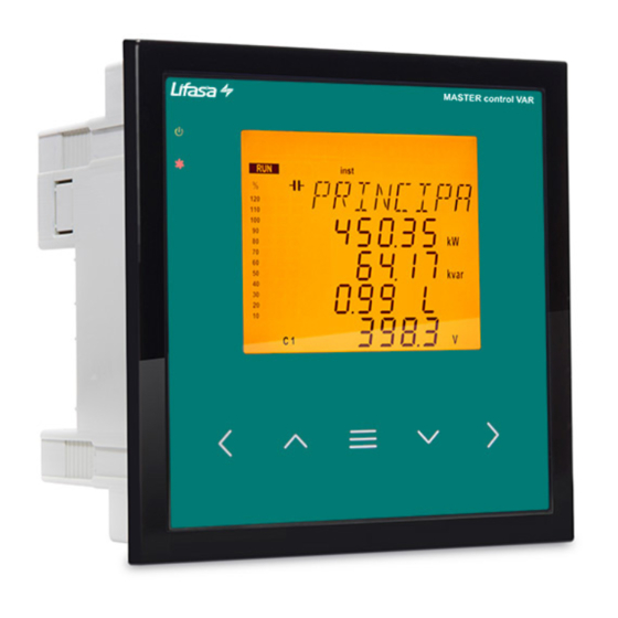
Controller MASTER control VAR FAST 2�- PRODUCT DESCRIPTION The Controller MASTER control VAR FAST reactive energy regulator is a unit that measures the grid cosine and regulates capacitor connection and disconnection in order to correct it. It also calculates and displays the main electrical parameters of balanced or unbalanced sin- gle-phase and three-phase networks. -
Page 9: 3�- Unit Installation
The Controller MASTER control VAR FAST unit must be installed by authorised and quali- fied staff. The power supply plug must be disconnected and measuring systems switched off before han- dling, altering the connections or replacing the unit. -
Page 10: 3�2�- Installation
The safe use of the Controller MASTER control VAR FAST requires the persons installing or handling it to follow the general safety measures of LV electrical installations, as well as the warnings indicated in this instruction manual. - Page 11 Controller MASTER control VAR FAST CORRECT INCORRECT LOAD CAPACITORS LOAD CAPACITORS LOAD CAPACITORS The current transformers (CT) must I f t h e C Ts a r e c o n n e c t e d If the CTs are connected in this...
-
Page 12: 3�4�- Unit Terminals
Controller MASTER control VAR FAST 3.4.- UNIT TERMINALS Table 2:List of Controller MASTER control VAR FAST terminals� Terminals of the top side of the unit 1: A1, Auxiliary power supply. 23: 8, Output 8 2: A2, Auxiliary power supply. 24: 9, Output 9... - Page 13 Controller MASTER control VAR FAST 7 8 9 10 11 12 28 29 30 31 32 33 34 35 36 37 38 39 40 41 Figure 2: Controller MASTER control VAR FAST terminals� Instruction Manual...
-
Page 14: 3�5�- Connection Diagram
ACT C1...C6 COM 1 2 3 4 5 6 Figure 3: 3 voltages + Neutral and 3 currents, Controller MASTER control VAR FAST 6 model� Note: If the connection layout mentioned above is not respected, you must adjust the phase following the procedure described in section "5�6�- PHASE CONNECTION”... -
Page 15: 3�5�2�- 3 Voltages + Neutral And 3 Currents, Controller Master Control Var
COM 1 2 3 4 5 6 7 8 9 10 11 12 Figure 4: 3 voltages + Neutral and 3 currents, Controller MASTER control VAR FAST 12 model� Note: If the connection layout mentioned above is not respected, you must adjust the phase following the procedure described in section "5�6�- PHASE CONNECTION”... -
Page 16: 3�5�3�- 3 Voltages + Neutral And 1 Current, Controller Master Control Var
ACT C1...C6 COM 1 2 3 4 5 6 Figure 5: 3 voltages + Neutral and 1 current, Controller MASTER control VAR FAST 6 model� Note: If the connection layout mentioned above is not respected, you must adjust the phase following the procedure described in section "5�6�- PHASE CONNECTION”... -
Page 17: 3�5�4�- 3 Voltages + Neutral And 1 Current, Controller Master Control Var
COM 1 2 3 4 5 6 7 8 9 10 11 12 Figure 6: 3 voltages + Neutral and 1 current, Controller MASTER control VAR FAST 12 model� Note: If the connection layout mentioned above is not respected, you must adjust the phase following the procedure described in section "5�6�- PHASE CONNECTION”... -
Page 18: 3�5�5�- 2 Voltages And 1 Current, Controller Master Control Var Fast 6 Model
ACT C1...C6 COM 1 2 3 4 5 6 Figure 7: 2 voltages and 1 current, Controller MASTER control VAR FAST 6 model� Note: If the connection layout mentioned above is not respected, you must adjust the phase following the procedure described in section "5�6�- PHASE CONNECTION”... -
Page 19: 3�5�6�- 2 Voltages And 1 Current, Controller Master Control Var Fast 12 Model
COM 1 2 3 4 5 6 7 8 9 10 11 12 Figure 8: 2 voltages and 1 current, Controller MASTER control VAR FAST 12 model� Note: If the connection layout mentioned above is not respected, you must adjust the phase following the procedure described in section "5�6�- PHASE CONNECTION”... -
Page 20: 3�5�7�- Leakage Current Connection, Iδ
Controller MASTER control VAR FAST 3�5�7�- LEAKAGE CURRENT CONNECTION, IΔ To measure the leakage current, an earth leakage transformer must be used, such as WGS. The leakage current transformer must be connected such as to measure the current of the capacitor bank. -
Page 21: 3�6�- Starting Up The Unit
Controller MASTER control VAR FAST 3.6.- STARTING UP THE UNIT Once the Controller MASTER control VAR FAST is powered on, the following screen appears on the display, , which shows the name of the unit, the version and the model. -
Page 22: 4�- Operation
Power Figure 11: Measurement and Compensation in the four quadrants� In addition to the basic functions of any regulator the Controller MASTER control VAR FAST: Performs the functions of a network analyzer, measuring and displaying multiple parameters. Has a Plug&Play function for automatic configuration of the unit. -
Page 23: 4�1�- Definitions
Controller MASTER control VAR FAST 4.1.- DEFINITIONS This section provides a number of definitions that may be useful for understanding the opera- tion of the unit. 4�1�1 FOUR-QUADRANT REGULATOR� This means that the regulator is capable of performing the measurement and regulation func-... -
Page 24: 4�1�5� Plug And Play
This time is necessary for the capacitor to discharge enough so that, when it is reconnected, it does not cause overcurrents in the system. Both Ton and Trec have different time bases for the Controller MASTER control VAR (in sec- onds) and for the Controller MASTER control VAR FAST (in network cycles). -
Page 25: 4�2�- Measurement Parameters
%, of the RMS value of the harmonic content and the value of the fun- damental component. 4.2.- MEASUREMENT PARAMETERS The unit displays the following electrical parameters: 3U.3C 4�2�1� CONNECTION TYPE: 3U.3C Table 3: Controller MASTER control VAR FAST measurement parameters ( connection) Parameter Units Phases Total L1-L2-L3 Phase-neutral voltage ... -
Page 26: 4�2�2� Connection Type: 3U.1C
Controller MASTER control VAR FAST 3U.1C 4�2�2� CONNECTION TYPE: 3U.1C Table 4: Controller MASTER control VAR FAST measurement parameters ( connection) Parameter Units Phases Total L1-L2-L3 Phase-neutral voltage Phase-phase voltage Current (L1) ... -
Page 27: 4�2�3� Connection Type: 2U.1C
Controller MASTER control VAR FAST 2U.1C 4�2�3� CONNECTION TYPE: 2U.1C Table 5: Controller MASTER control VAR FAST measurement parameters ( connection) Parameter Units Phases Total L1-L2-L3 Phase-neutral voltage Phase-phase voltage (L1-L2) Current (L1) Leakage current ... -
Page 28: 4�3�- Key Functions
Controller MASTER control VAR FAST 4.3.- KEY FUNCTIONS The Controller MASTER control VAR FAST has 5 keys that can be used to browse the vari- ous screens and program the unit. Key functions on the measurement screens ( Table 6 Table 6: Key functions on the measurement screens�... - Page 29 Controller MASTER control VAR FAST Key functions on the Configuration and Test screens, editing mode ( Table 8 Table 8: Key functions on the Configuration and Test screens, edit mode. Short press Increase the value or show the next option.
-
Page 30: 4�4�- Display
Analogue bar Data area Figure 12: Areas of the Controller MASTER control VAR FAST display� The data area: displays the instantaneous, maximum and minimum values of each one of the phases which the unit is measuring or calculating. -
Page 31: 4�4�1� Status Of The Capacitors
Controller MASTER control VAR FAST Estado dos 4�4�1� STATUS OF THE CAPACITORS condensadores Estado do Figure 13: Status of the capacitors� Barra analógica equipamento This area shows the status of the relays (stages) of the unit, and thus of the capacitors con- nected to it. -
Page 32: 4�4�3� Analogue Bar
Controller MASTER control VAR FAST 4�4�3� ANALOGUE BAR Figure 14: Analogue Bar This bar is displayed on the measurement screens, and can show: the current of each phase as a percentage. the current THD of each phase. the power connected to the capacitor bank. -
Page 33: 4�5�- Led Indicators
A Fan LED: Indicates that the fan is operating. A key pressed LED: Lights up when any of the 5 keys are pressed. Alarm Key pressed Figure 15:LED indicators of the Controller MASTER control VAR FAST� Instruction Manual... -
Page 34: 4�6�- Operating States
( Figure 12 It is the normal operating status of the Controller MASTER control VAR FAST, in which the unit measures the various grid parameters and acts according to the configured parameters, connecting or disconnecting the capacitors from the capacitor bank. - Page 35 Controller MASTER control VAR FAST Phase - Neutral Voltages Parameters L1 Phase - Neutral Voltage (V or kV) L2 Phase - Neutral Voltage (V or kV) L3 Phase - Neutral Voltage (V or kV) Phase - Neutral Voltage III(V or kV) Display the minimum values.
- Page 36 Controller MASTER control VAR FAST Cosine Parameters φ L1 Cos φ L2 Cos φ L3 Cos φ φ III L: Inductive / C: capacitive +: Consumed / -: generated Display the minimum values. Display the maximum values. Press the key to switch to the Energy III consumed screen.
- Page 37 Controller MASTER control VAR FAST Active Power Parameters L1 Active power (kW or MW) L2 Active power (kW or MW) L3 Active power (kW or MW) Active Power III(kW or MW) Display the minimum values. Display the maximum values. Inductive Reactive Power...
- Page 38 Controller MASTER control VAR FAST Apparent Power Parameters Apparent Power Apparent Power Apparent Power Apparent Power (kVA or MVA) Display the minimum values. Display the maximum values. Leakage current / Frequency Parameters / Temperature Leakage current (mA) Frequency (Hz) Temperature (ºC) Display the minimum values.
- Page 39 Controller MASTER control VAR FAST Voltage harmonics Parameters L1 Voltage harmonic L2 Voltage harmonic L3 Voltage harmonic Change the harmonic no.: 3, 5, 7, 9, 11, 13, 15, 17. Display the maximum values. Current THD Parameters L1 Current THD L2 Current THD L3 Current THD Display the maximum values.
- Page 40 Controller MASTER control VAR FAST Energy III consumed Parameters Active Energy III consumed (kWh or MWh) Inductive Reactive Energy III consumed (kvarLh or MvarLh) Capacitive Reactive Energy III consumed (kvarCh or MvarCh) Apparent Energy III consumed (kVAh or MVAh) Press the key to switch to the Main screen.
- Page 41 Controller MASTER control VAR FAST Active alarms Parameters Active alarm code E01 to E017 Table 9 I f t h e r e a r e m o r e t h a n 4 a l a r m s , t h e information is scrolled on the screen.
- Page 42 In these alarms, two levels have been configured: The Lo value: When the unit exceeds this value for 30 minutes, the corresponding alarm is triggered and, if alarm E11 is enabled, the Controller MASTER control VAR FAST unit enters No Connection status and activates alarm E11.
- Page 43 Controller MASTER control VAR FAST 3U.1C 4�6�1�2� Connection (3 Voltages + Neutral and 1 current) Main Screen Parameters Active Power III(kW or MW) Reactive Power III(kvar or Mvar) +: inductive / -: capacitive φ L: Inductive / C: capacitive +: consumed / -: generated Phase - Phase Voltage III(V or kV) Display the minimum values.
- Page 44 Controller MASTER control VAR FAST Currents Parameters Current (A) Display the minimum values. Display the maximum values. Press the key to switch to the Cosine screen. φ Cosine Parameters φ φ L: Inductive / C: capacitive +: consumed / -: generated Display the minimum values.
- Page 45 Controller MASTER control VAR FAST Power III Parameters Active Power III(kW or MW) Inductive Reactive Power III (kvarL or MvarL) Capacitive Reactive Power III (kvarC or MvarC) Apparent Power III (kVA or MVA) Display the minimum values. Display the maximum values.
- Page 46 Controller MASTER control VAR FAST Voltage harmonics Parameters L1 Voltage harmonic L2 Voltage harmonic L3 Voltage harmonic Change the harmonic no.: 3, 5, 7, 9, 11, 13, 15, 17. Display the maximum values. Current THD Parameters Current THD (%) Display the maximum values.
- Page 47 Controller MASTER control VAR FAST Energy III consumed Parameters Active Energy III consumed (kWh or MWh) Inductive Reactive Energy III consumed (kvarLh or MvarLh) Capacitive Reactive Energy III consumed (kvarCh or MvarCh) Apparent Energy III consumed (kVAh or MVAh) Press the key to switch to the Main screen.
- Page 48 Controller MASTER control VAR FAST Active alarms Parameters Active alarm code E01 to E017 Table 9 I f t h e r e a r e m o r e t h a n 4 a l a r m s , t h e information is scrolled on the screen.
- Page 49 Controller MASTER control VAR FAST 2U.1C 4�6�1�3� Connection (2 Voltages and 1 current) Main Screen Parameters Active Power III(kW or MW) Reactive Power III(kvar or Mvar) +: inductive / -: capacitive φ L: Inductive / C: capacitive +: consumed / -: generated Phase - Phase Voltage (V or kV) Display the minimum values.
- Page 50 Controller MASTER control VAR FAST Cosine Parameters φ φ L: Inductive / C: capacitive +: consumed / -: generated Display the minimum values. Display the maximum values. Press the key to switch to the Energy III consumed screen. Power Factor...
- Page 51 Controller MASTER control VAR FAST Leakage current / Frequency Parameters / Temperature Leakage current (mA) Frequency (Hz) Temperature (ºC) Display the minimum values. Display the maximum values. Voltage THD Parameters Voltage THD (%) Display the maximum values. Voltage harmonics Parameters Voltage harmonic (%) Change the harmonic no.:...
- Page 52 Controller MASTER control VAR FAST Current THD Parameters Current THD (%) Display the maximum values. Current harmonics Parameters Current harmonic (%) Change the harmonic no.: 3, 5, 7, 9, 11, 13, 15, 17. Display the maximum values. Energy III consumed...
- Page 53 Controller MASTER control VAR FAST Energy III generated Parameters Active Energy III generated (kWh or MWh) Inductive Reactive Energy III generated (kvarLh or MvarLh) Capacitive Reactive Energy III generated (kvarCh or MvarCh) Apparent Energy III generated (kVAh or MVAh) Operations Parameters No�...
-
Page 54: 4�6�2� Test Status
Controller MASTER control VAR FAST 4�6�2� TEST STATUS This status is identified by the symbol in the unit status area of the display ( Figure 12 The stages can be connected and disconnected manually, and the measured parameters that relate to each one of the stages can be displayed. It also comprises the AutoTest function, which scans and calculates all the stages of the unit. - Page 55 Controller MASTER control VAR FAST Once the AutoTest has started, the results of the capacitors that are connected and disconnected are shown: Leakage current (mA) Capacitive Reactive Power (kvarC or MvarC) Capacitive Power % of each capacitor relative to the total estimated value.
- Page 56 Controller MASTER control VAR FAST Cosine φ test Parameters Display screen of the: 2U.1C and 3U.1C connection) φ ( L1 Cos 3U.3C connection) φ ( L2 Cos 3U.3C connection) φ ( L3 Cos 3U.3C connection) φ ( 3U.3C connection) φ III(...
-
Page 57: 4�7�- Inputs
Controller MASTER control VAR FAST 4.7.- INPUTS The Controller MASTER control VAR FAST comprises two digital inputs (terminals 31 and 32 ) for activating any of the four target cos , in other words, the desired power factor Figure 2 φ... -
Page 58: 4�9�- Rs-485 Communications
Controller MASTER control VAR FAST and the master unit of 1,200 metres. A maximum of 32 Controller MASTER control VAR FAST units can be connected to this bus. Use an intelligent RS-232 to RS-485 network protocol converter (M54020 intelligent converter) to establish the communications with the master unit. -
Page 59: 4�9�2� Protocol
It allows individual master-slave dialogue and also enables commands in broadcast format. In the Modbus protocol, the Controller MASTER control VAR FAST unit uses the RTU (Remote Terminal Unit) mode. In the RTU mode, the message start and end are detected with silences of at least 3.5 characters, and the 16-bit CRC error-detection method is used. -
Page 60: 4�9�3� Modbus Memory Map
Controller MASTER control VAR FAST 4�9�3� MODBUS MEMORY MAP A.- Measurement Variables For these variables Function 04 is implemented: reading logs. The Modbus addresses of all the tables are hexadecimal. Table 12: Modbus memory map: measurement variables (Table 1) Parameter... - Page 61 Controller MASTER control VAR FAST Table 12 (Continuation): Modbus memory map: measurement variables (Table 1) Parameter Instantaneous Maximum Minimum Units Three-phase voltage 4E-4F 24E-24F 34E-34F V/100 Three-phase current 50-51 250-251 350-351 Three-phase active power 52-53 252-253 352-353 Three-phase inductive power...
- Page 62 Table 14:Modbus memory map: measurement variables (Table 3) Parameter Instantaneous Relay variable Alarm variable 605-606 Status of the outputs Status of the digital inputs No. of connections, of each of the 12 outputs 625-63C (6 in the Controller MASTER control VAR FAST 6 model) Instruction Manual...
- Page 63 Controller MASTER control VAR FAST OptoMOS relay outputs variable Shows the status of the 12 (Controller MASTER control VAR FAST 12 model) or 6 (Control- ler MASTER control VAR FAST 6 model) optoMOS relay outputs. It is a 16-bit variable in which each bit indicates the status of an output.
- Page 64 Controller MASTER control VAR FAST B.- Programming variables The following functions are implemented for these variables: Function 04: reading logs. Function 10: Writing multiple logs. Table 15:Modbus memory map: programming variables (Table 1) Unit parameters Configuration variable Address Serial number...
- Page 65 Controller MASTER control VAR FAST Current 1 is assigned to voltage 1 in the direct direction, current 2 is assigned to voltage 2 in the reverse direction and current 3 is assigned to voltage 3 in the direct direction. Table 20:Modbus memory map: programming variables (Table 6)
- Page 66 Table 26:Modbus memory map: programming variables (Table 12) No� of stages Configuration variable Address Valid data margin Default value 0-6 (Controller MASTER control VAR FAST 6) No. of stages 113B 0-12 (Controller MASTER control VAR FAST 12) Table 27:Modbus memory map: programming variables (Table 13)
- Page 67 Controller MASTER control VAR FAST Table 33:Modbus memory map: programming variables (Table 19) Alarm: Fan Configuration variable Address Valid data margin Default value Value 114C 0 - 80 ºC Enabled 114D 0 (OFF), 1 (ON) Table 34:Modbus memory map: programming variables (Table 20)
-
Page 68: 4�9�4� Example Of A Modbus Query
Controller MASTER control VAR FAST Table 36 (Continuation): Modbus memory map: programming variables (Table 22) Enabling alarms Configuration variable Address Valid data margin Default value Output associated with Alarm E01 1170 Output associated with Alarm E02 1171 Output associated with Alarm E03... -
Page 69: 4�10�- Cpc-Net Communications
If communications are used, they must be connected to CPC3i-xRS zero switching control boards. The Controller MASTER control VAR FAST connection with the board will be made through the CPC-NET channel, in accordance with the connection table, . Also consult the ter-... -
Page 70: 4�10�1� Modbus Control Frame
Note: The frame asks for the transmission of data to thyristors in up to 16 different steps, phase by phase. The Controller MASTER control VAR FAST regulator has a maximum of 12 outputs, so it does not use the last 4 steps of the frame. -
Page 71: 5�- Configuration
Controller MASTER control VAR FAST 5�- CONFIGURATION The various configuration parameters of the unit can be consulted and edited in the unit setup menu. The unit always keeps the capacitors disconnected (except in the Plug&Play function). This status is identified by the... -
Page 72: 5�1�- Plug&Play
Controller MASTER control VAR FAST 5.1.- PLUG&PLAY The Plug&Play function assists the user during the configuration of the unit, since it automatically configures the basic parameters that are required for the unit to perform its regulation functions correctly. To start the Plug&Play process, press the The process enters editing mode. - Page 73 Controller MASTER control VAR FAST Connection type: 3U�3C: 3 voltages and 3 currents� 3U�1C: 3 voltages and 1 current� 2U�1U: 2 voltages and 1 current� Phase φ III L: Inductive / C: capacitive +: consumed / -: generated Press the key to switch to the next screen of results.
- Page 74 Controller MASTER control VAR FAST Table 40 (Continuation): Code of Plug&Play errors� Code Description Error in the measurement of the largest capacitor. No capacitors found. Incorrect measurement of the number of capacitors. Incorrect measurement of the ratio of the first capacitor.
-
Page 75: 5�2�- Current Transformation Ratio
Controller MASTER control VAR FAST 5.2.- CURRENT TRANSFORMATION RATIO The primary and secondary value of the current transformer is configured in this point. Press the key to enter editing mode. It is identified by the symbol and the blinking of the digits to be modified. -
Page 76: 5�3�- Target Cos
φ factor required for the installation. The Controller MASTER control VAR FAST will add the number of capacitors needed to adjust the value as close as possible to the objective value. Since the... -
Page 77: 5�4�- Connection And Reconnection Time
Controller MASTER control VAR FAST 5.4.- CONNECTION AND RECONNECTION TIME In this point the action times of the device are configured in seconds: is the minimum time between the connection and disconnection of a single stage (counted in number of network cycles). -
Page 78: 5�5�- Connection Type
Controller MASTER control VAR FAST 5.5.- CONNECTION TYPE In this point the connection type of the installation is selected, where: 3u3C : 3 voltages + neutral and 3 currents. 3u1C : 3 voltages + neutral and 1 current. 2u1C : 2 voltages and 1 current. - Page 79 Controller MASTER control VAR FAST Press the key to enter editing mode. It is identified by the symbol and the blinking of the digits to be modified. key shows the next option. key shows the previous option. Press to validate the data; the symbol disappears from the display.
-
Page 80: 5�7�- No� Of Stages
Depending on whether the model is Controller MASTER control VAR FAST 6 or Controller MASTER control VAR FAST 12, it can be configured with up to 6 or up to 12 outputs. Press the key to enter editing mode. It is identified by the symbol and the blinking of the digits to be modified. -
Page 81: 5�8�- Program
Controller MASTER control VAR FAST 5.8.- PROGRAM The unit is made up of stages with different powers. The base power (value 1) will be that of the stage with the lowest power. The powers of all the other stages will depend on the power of the first stage. -
Page 82: 5�9�- C/K Factor
Controller MASTER control VAR FAST 5.9.- C/K FACTOR The C/K factor is adjusted according to the reactive current provided by the smallest stage, measured in the secondary of the current transformer (CT). The adjustment value of this factor therefore depends on the power of the smallest stage, the ratio of the CTs and the network voltage. - Page 83 Controller MASTER control VAR FAST For other voltages or conditions not included in the table, the value of C/K can be obtained by means of a simple calculation. Calculating the C/K Factor The equation for calculating the C/K factor is: ⋅...
-
Page 84: 5�10�- Advanced Setup
Controller MASTER control VAR FAST Press the key to enter editing mode. It is identified by the symbol and the blinking of the digits to be modified. key increases the digit value. key decreases the digit value. key skips to the previous digit. -
Page 85: 5�11�- Voltage Transformation Ratio
Controller MASTER control VAR FAST key shows the previous option. Press to validate the data; the symbol disappears from the display. Press the key to access the next programming step. If no keys are pressed for 5 minutes, the unit switches to the simulation screen, “5.27.-... -
Page 86: 5�12�- Status Of The Stages
Controller MASTER control VAR FAST Press the key to access the next programming step. If no keys are pressed for 5 minutes, the unit switches to the simulation screen, “5.27.- SIMULATION SCREEN” 5.12.- STATUS OF THE STAGES This parameter is repeated for each of the 6 or 12... -
Page 87: 5�13�- Display
Controller MASTER control VAR FAST 5.13.- DISPLAY In this point the lighting status of the screen and its language can be configured. Press the key to enter editing mode. It is identified by the symbol and the blinking of the digits to be modified The following display configuration options are available: : the display light is always on. -
Page 88: 5�14�- Analogue Bar
Controller MASTER control VAR FAST 5.14.- ANALOGUE BAR At this point the parameter to be displayed in the analogue bar is configured ( "4.4.3. ANALOGUE BAR” Press the key to enter editing mode. It is identified by the symbol and the blinking of the digits to be modified. -
Page 89: 5�15�- Fan
Controller MASTER control VAR FAST 5.15.- FAN In this point the activation of the relay output associated with the fan can be configured. It is possible to configure whether it is enabled or not , as well as the temperature above which it is to be activated or deactivated. -
Page 90: 5�16�- Rs-485 Communications
Controller MASTER control VAR FAST 5.16.- RS-485 COMMUNICATIONS In this point the RS-485 communication parameters can be configured. Press the key to enter editing mode. It is identified by the symbol and the blinking of the digits to be modified. -
Page 91: 5�17�- Cpc-Net Communications
Controller MASTER control VAR FAST 5.17.- CPC-NET COMMUNICATIONS In this point the CPC-NET communication parameters can be configured. Press the key to enter editing mode. It is identified by the symbol and the blinking of the digits to be modified. -
Page 92: 5�18�- Clear
Controller MASTER control VAR FAST 5.18.- CLEAR In this point it is possible to configure whether or not to delete ( ) the maximum and minimum values, the energies and the number of connections of the stages. Press the key to enter editing mode. It is... -
Page 93: 5�19�- Enabling Alarms
Controller MASTER control VAR FAST 5.19.- ENABLING ALARMS This screen is repeated for every type of Error or Alarm (from ); see In it the Table 9� enabling or disabling of each error or alarm can be configured, as can whether or not to associate it with the activation of a relay or a digital output. -
Page 94: 5�20�- Voltage Alarms
Controller MASTER control VAR FAST 5.20.- VOLTAGE ALARMS In this point the phase-phase voltage thresholds above which the overvoltage alarm ( ) and the no voltage alarm ( ) should be triggered can be configured. The alarm must be enabled ( “5.19.- ENABLING... -
Page 95: Alarm
Controller MASTER control VAR FAST 5.21.- COS ALARM φ In this point the limit for action of the cos φ alarm can be configured. It is activated every time the value of the cos φ drops below the configured value and the current is higher than programmed. -
Page 96: 5�22�- Voltage Thd Alarm
30 seconds, alarm is triggered, and if alarm is enabled, the Controller MASTER control VAR FAST unit enters Disconnection status and activates alarm If the unit falls back under the value for 10 minutes, it deactivates the alarms and returns to the normal operating status. -
Page 97: 5�23�- Current X I Thd Alarm
30 seconds, alarm is triggered, and if alarm is enabled, the Controller MASTER control VAR FAST unit enters the Disconnection status and activates alarm If the unit falls back under the value for 10 minutes, it deactivates the alarms and returns to the normal operating status. -
Page 98: 5�24�- Temperature Alarm
The value: if the unit exceeds this value for 30 seconds, alarm is triggered, is enabled, the Controller MASTER control VAR FAST unit enters and if alarm Disconnection status and activates alarm If the unit falls back under the value for 10 minutes, it deactivates the alarms and returns to the normal operating status. - Page 99 Controller MASTER control VAR FAST In the No Connection status, the unit does not connect the stages, but also does not disconnect them if the operation requires it. In the Disconnection status, it disconnects all the stages and does not allow them to connect.
-
Page 100: 5�25�- Leakage Current Alarm
Controller MASTER control VAR FAST 5.25.- LEAKAGE CURRENT ALARM In this point the parameters of the leakage current alarm can be configured. Four alarms are linked to the leakage current: The alarms must be enabled ( “5.19.- ENABLING ALARMS”) Press the key to enter editing mode. -
Page 101: 5�26�- No� Of Operations Alarm
Controller MASTER control VAR FAST 5.26.- NO. OF OPERATIONS ALARM In this point the number of operations of any of the stages above which the alarm will be triggered can be configured. The alarms must be enabled ( “5.19.- ENABLING ALARMS”) -
Page 102: 5�27�- Simulation Screen
Controller MASTER control VAR FAST 5.27.- SIMULATION SCREEN This screen can be accessed by pressing the key for more than 3 seconds, in order to exit the configuration status. This is an informative, non-editable screen. The simulation screen provides certain information which can be used to decide to enter the... -
Page 103: 6�- Technical Features
Controller MASTER control VAR FAST 6�- TECHNICAL FEATURES AC Power supply Rated voltage 100 ... 520 V Frequency 50 ... 60 Hz Controller MASTER control Controller MASTER control VAR FAST 6 VAR FAST 12 Consumption 8 ... 14 VA 9... 15 VA... - Page 104 Maximum altitude 2,000 m IP31 Protection degree Front panel: IP51 Mechanical features Dimensions (Figure 19) 144x144x78 mm Weight 575 g Enclosure Self-extinguishing V0 plastic Assembly Panel 21.75 5.84 Figure 19: Dimensions of the Controller MASTER control VAR FAST� Instruction Manual...
- Page 105 Controller MASTER control VAR FAST Standards Safety requirements for electrical units for measurement, control and UNE-EN 61010:2010 laboratory use� Electromagnetic compatibility (CEM) UNE-EN 61000:2007 Electromagnetic compatibility (CEM)� Part 6: Generic standards� Sec- UNE-EN 61000-6-2:2005 tion 2: Generic immunity standards for industrial environments�...
-
Page 106: 7�- Maintenance And Technical Service
• LIFASA accepts no liability due to the possible damage to the unit or other parts of the installation, nor will it cover any possible sanctions derived from a possible failure, improper installation or “improper usage”... - Page 107 Controller MASTER control VAR FAST Instruction Manual...
- Page 108 LIFASA (INTERNATIONAL CAPACITORS, SA) C/Vallès 32, Pol. Ind. Can Bernades 08130 - Santa Perpètua de Mogoda (Barcelona) ESPAÑA Tel: (+34) 935 747 017 - Fax: (+34) 935 448 433 www.lifasa.es info@lifasa.es...
Need help?
Do you have a question about the MASTER control Var and is the answer not in the manual?
Questions and answers