Table of Contents
Advertisement
Advertisement
Table of Contents

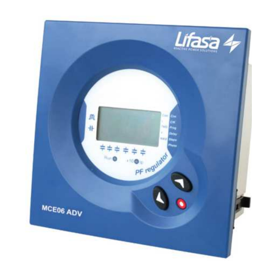
Summary of Contents for Lifasa MCE06ADV
- Page 1 POWER FACTOR REGULATORS MCE06ADV – MCE12ADV Instructions Manual...
- Page 2 Controllers MCE06ADV – MCE12ADV - 1 -...
-
Page 3: Table Of Contents
Controllers MCE06ADV – MCE12ADV Index ______________________________________________________________ INTRODUCTION AND SAFETY RECOMMENDATIONS ................. 3 ..........................3 ELIVERY SPOT CHECK ............................4 TARTING SCREEN ..............................4 EFINITIONS 1.3.1 Four quadrant regulators ........................4 1.3.2 FCP program (FAST Computerized Program)..................4 1.3.3 Stages and steps ............................ 4 1.3.4... -
Page 4: Introduction And Safety Recommendations
Controllers MCE06ADV – MCE12ADV INTRODUCTION AND SAFETY RECOMMENDATIONS INTERNATIONAL CAPACITORS, S.A. would like to thank you for showing your trust by choosing one of our MCExxADV series regulators. These units are constructed with the latest state-of-the-art technology, including a powerful processor to calculate the optimum algorithms for achieving the best compensation of cosφ. -
Page 5: Starting Screen
Controllers MCE06ADV – MCE12ADV Fig. 1.1.- Rear face label Starting screen When the MCExxADV is started (just after supply connection) the screen shows a code indicating the device version. It’s important to indicate this code in case of reporting any device fault or error. -
Page 6: General Characteristics
Wide choice of switching programs: 1:1:1, 1:2:2, 1:2:4 , 1:1:2:2, etc. which allows the split up of the total power into up to 31 steps in MCE06ADV or up to 79 steps in MCE12ADV. Four quadrants control (see fig.2.1) , display of the connected stages, of cosφ and active and... -
Page 7: Front Panel: Screen And Keyboard
Controllers MCE06ADV – MCE12ADV FRONT PANEL: SCREEN AND KEYBOARD The PF regulator’s front panel shows the following items: Front Screen Configurable Parameters Measured Parameters Navigation keys Fig. 3.1.- Front cover and screen NOTE: The set-up procedure, the description of different... -
Page 8: Display Screen
Overvoltage. The measured voltage exceeds the rated voltage by a +15%. Alarm relay In case that the number of stages configured in a MCE06ADV or MCE12ADV , is less than 6 or 12 respectively, the relay number 6 or 12 is automatically configured as alarm relay. The relay remains connected in absence of alarm (positive safety) and disconnects in case that one or more of the errors listed in section 3.2 occur. -
Page 9: Regulator Status And Key Functions
Controllers MCE06ADV – MCE12ADV Regulator status and key functions MCExxADV regulators have two possible status. Normal or RUN Status: This is the normal working status of the regulator. In such status the device measures and displays the cosϕ of the loads and automatically regulates the connection and disconnection of capacitors in order to compensate according to programmed target value. -
Page 10: Installation And Start Up
Controllers MCE06ADV – MCE12ADV INSTALLATION AND START UP This section contains information instructions and warnings that the user must follow by its own security and to ensure safe operation of the device. WARNING! MCExxADV regulators are usually connected to equipment containing capacitors, which remain charged after removing supply voltage. -
Page 11: Device Installation
Controllers MCE06ADV – MCE12ADV DEVICE INSTALLATION 4.2.1 Mechanical Installation Mechanically, the device is intended to be mounted attached to the front door of the cabinet. The fitting hole must be according to DIN 43 700, (dimensions 138 x138 mm). 4.2.2... -
Page 12: Cabling Cross Sections And Protections
RELAYS C1..C6 Relay Output 4 Relay Output 5 Relay Output 6 Supply/Measure Input 0V Supply/Measure Input(*) Fig. 4.2.- Connection schematic for MCE06ADV (*) Rated voltage depending on type. See device label MCE12ADV SUPPLY AND MEASURE TERMINALS Nº Terminals description Current input S1... -
Page 13: Configurable Parameters
Controllers MCE06ADV – MCE12ADV CONFIGURABLE PARAMETERS In order to adapt the regulator to the loads, certain parameters of the MCExxADV must be set-up. The programmable parameters, the required settings and the set-up procedure are explained here below. See also paragraph 3.5.2 to see how to select the different menu options. -
Page 14: C/Kparameter Calculation
Controllers MCE06ADV – MCE12ADV C/K parameter calculation For conditions other than those given in table 5.1 the parameter C/K can be calculated as follows. The necessary data to perform the calculation are: The power of the smaller capacitor step, Q, the supply voltage, V and the current transformer ratio, K &... -
Page 15: Selection Of The Number Of Stages
This setting allows the selection of the number of stages of the PF compensation equipment. Depending on the device type, MCE06ADV or MCE12ADV we can select up to 6 or 12 stages. If the number of stages is less than 6 or 12 respectively in MCE06ADV or MCE12ADV the relay number 6 or 12 is automatically assigned as alarm relay (see paragraph 3.3) -
Page 16: Navigation Schematic
Controllers MCE06ADV – MCE12ADV Navigation schematic. Tabla 6-1.- Menu navigation schematic Parameter Device screen display selection paragraph Long push to start set-up Target cosϕ Starting screen Program Delay times Nr of stages CT phase CT primary current ! ! ! ! IMPORTANT! : While the device is in set-up mode, if there isn’t any key pushing for more than 3 minutes, the device... -
Page 17: Run Status
Controllers MCE06ADV – MCE12ADV RUN STATUS Once the device has been configured according to installation needs it can be set to RUN mode to regulate the PF of the installation. RUN mode is the default mode after exiting the set-up menu or after the device start (supply connection followed by a short initialisation period). -
Page 18: Mcexxadv Behaviour In Alarm Mode
Controllers MCE06ADV – MCE12ADV MCExxADV behaviour in ALARM mode In case that the MCExxADV detects an error during normal operation (see paragraph 3.2) the screen displays an error code and the behaviour of the device is as described in table 7-.1.


Need help?
Do you have a question about the MCE06ADV and is the answer not in the manual?
Questions and answers