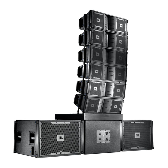
Summary of Contents for JBL VerTec VT4889
- Page 1 System Configuration Manual Using crown I-Tech series For models VT4889, VT4888, VT4887, VT4881, VT4880...
-
Page 2: Table Of Contents
TABLE OF CONTENTS PAGE GENERAL AMPLIFICATION NOTES & REQUIREMENTS…………………. SUBWOOFER WIRING NOTES………………………………………………… STANDARD AMPLIFICATION RACK NOTES REGARDING LIMITER SETTINGS……………………………..…….. VT4887 & VT4881 TRANSDUCER COMPLEMENT.………………………………….…….. AMPLIFIER CONFIGURATION OPTIONS VT4887 & VT4881 ARRAY WIRING……………………………………………. VT4888 TRANSDUCER COMPLEMENT………………………………………… AMPLIFIER CONFIGURATION OPTIONS VT4888 ARRAY WIRING………………………………………………………... VT4889 TRANSDUCER COMPLEMENT…………………………………………... -
Page 3: General Amplification Notes & Requirements
Users may choose to use the same size amplifier to power all components / passbands. o DSP crossover presets provided by JBL assume that the same amplifier models with equal voltage gain, are used for each bandpass. -
Page 4: Subwoofer Wiring Notes
NOTES ON SUBWOOFER WIRING o VT4880: users may choose to wire both 2258 (18”) components in parallel to one (1) channel of a an I-T amp for (4) ohms load. In this case each amplifier channel drives one VT4880. If two VT4880 are wired in parallel, the load is two ohms. -
Page 5: Notes Regarding Limiter Settings
NOTES REGARDING LIMITER SETTINGS • The recommended limiter threshold settings provide 3 dB of headroom before the component or bandpass peak voltage is reached. • The component or bandpass peak voltage is 6 dB above the voltage used at continuous maximum power. -
Page 6: Vt4887 & Vt4881 Transducer Complement
VT4887 & VT4881 Transducer Complement: Nominal Nominal AES Power Peak Power Recommended Speakon NL8 Impedance Impedance 100 HR Model Per box Rating per Power Terminals Rating per Transducer per Passband transducer Passband Transducer 8Ω 8Ω HF 2407H Pins 4± 100W 450W MF 2104H Pins 4±... -
Page 7: Vt4887 & Vt4881 Array Wiring
JBL VerTec VT4887 with VT4881 Power Amplifier configurations - 4 +2 Box Array 2 I-T6000 Power Amplifiers IMPORTANT NOTES; All wiring configurations shown above use 8-conductor speaker cables terminated with Neutrik NL8 "Speakons". Ensure that each conductor in the cable is a minimum of #13 AW (3-4mm). -
Page 8: Transducer Complement
VT4888 Transducer Complement: Nominal Nominal AES Power Speakon Peak Power Recommended Impedance Impedance 100 HR Model Rating per Power per Rating per Terminals Transducer Passband transducer Passband Transducer 8Ω 2431H Pins 4± 16Ω 300W 300W 2106H Pins 3± 8Ω 8Ω 100W 400W 800W... - Page 9 Amplifier Configurations: Six VT4888 / Two I-T4000, Two I-T8000 Amplifier Power Bandpass Speakon Nominal Power Limiter Amplifier Available Peak Amplifier Driving Impedance Rating at Threshold Channel to Each Voltage Terminals at Pins Nominal Bandpass Impedance Ch 1 Pins 4+/- 5.7 ohms 1700W 283W 2431H...
-
Page 10: Vt4888 Array Wiring
JBL VerTec VT4888 Line Array Power Amplifier configurations - 4 Box Array 4 x Power Amplifiers 3 x Power Amplifiers (recommended) (2Ω Load on LF Passband) IMPORTANT NOTES All wiring configurations shown above use 8-conductor speaker cables terminated with Neutrik NL8 "Speakons". -
Page 11: Vt4889
JBL VerTec VT4888 Line Array Power Amplifier configurations - 6 Box Array IMPORTANT NOTES All wiring configurations shown above use 8-conductor speaker cables terminated with Neutrik NL8 "Speakons". Ensure that each conductor in the cable is a minimum of #13 AWGuage (3-4mm). -
Page 12: Transducer Complement
VT4889 Transducer Complement: Nominal Nominal AES Power Speakon Peak Power Recommended Impedance Impedance 100 HR Rating Model Rating per Power per Terminals Transducer Passband transducer Passband Transducer HF 2435H Pins 4± 5.3Ω 16Ω 300W 300W MF 2250H Pins 3± 8Ω 8Ω... - Page 13 Six VT4889 / One I-T4000, Three I-T8000 Amplifier Power Bandpass Speakon Nominal Power Limiter Amplifier Available Peak Amplifier Driving Impedance Rating at Threshold Channel to Each Voltage Terminals at Pins Nominal Bandpass Impedance Ch 1 Pins 4+/- 5.7 ohms 1700W 200W 100V 2435H...
-
Page 14: Vt4889 Array Wiring
JBL VerTec VT4889 Line Array Power Amplifier configurations - 4 Box Array 3 x Power Amplifiers 4 x Power Amplifiers (2Ω Load on LF Passband) (recommended) IMPORTANT NOTES; All wiring configurations shown above use 8-conductor speaker cables terminated with Neutrik NL8 "Speakons". - Page 15 JBL VerTec VT4889 Line Array Power Amplifier configurations - 6 Box Array 4 x Power Amplifiers (recommended) IMPORTANT NOTES; All wiring configurations shown above use 8-conductor speaker cables terminated with Neutrik NL8 "Speakons". Ensure that each conductor in the cable is a minimum of #13 AWGuage (3-4 mm).
- Page 16 JBL VerTec VT4889 Line Array Power Amplifier configurations - 8 Box Array 4 x Power Amplifiers IMPORTANT NOTES; All wiring configurations shown above use 8-conductor speaker cables terminated with Neutrik NL8 "Speakons". Ensure that each conductor in the cable is a minimum of #11 AWGuage (3-4 mm). Users might also consider using TWO NL8 cables for each 4 boxes which are wired in parallel at the rack for a total of 4 cables running to the cluster.
-
Page 17: Vt4880 Transducer Complement & Amplifier Configuration
VT4880 Transducer Complement: Nominal Nominal AES Power Peak Power Recommende Speakon NL4 Impedance Impedanc 100 HR Model Rating per d Power per Terminals e per Rating per Transducer Passband transducer Passband Transducer 2 x 2258H Pins 1± & 2± 8Ω 8Ω... -
Page 18: Vt4880 Array Wiring
JBL VerTec VT4880 Power Amplifier configurations - 2 or 4 Box Arrays IMPORTANT NOTES; All wiring configurations shown above use 8-conductor speaker cables terminated with Neutrik NL4 "Speakons". Ensure that each conductor in the cable is a minimum of #11 AWGuage (3-4 mm). -
Page 19: Vertec Support Team And Weblinks
Email address: rgonzale@harman.com Email address: WEBLINKS JBL PROFESSIONAL: www.jblpro.com VERTEC PRODUCTS: www.jblpro.com/vertec1/new_vertec/ JBL CUSTOMER SERVICE: www.jblproservice.com VERTEC EMAIL ADDRESS: vertec@harman.com CROWN AMPLIFIERS: www.crownaudio.com JBL Professional 8500 Balboa Blvd. Northridge, CA 91329 818-894-8850 © 2005 JBL Professional Part # 350485-001 04/05...


Need help?
Do you have a question about the VerTec VT4889 and is the answer not in the manual?
Questions and answers