Advertisement
Quick Links
Specifications Information and Repair Parts Manual
Please read and save this Repair Parts Manual. Read this manual and the General Operating Instructions carefully before attempting to assemble, install, operate
or maintain the product described. Protect yourself and others by observing all safety information. The Safety Instructions are contained in the General Operating
Instructions. Failure to comply with the safety instructions accompanying this product could result in personal injury and/or property damage! Retain instructions
for future reference. AMT reserves the right to discontinue any model or change specifications at any time without incurring any obligation.
©2016 AMT Pump Company, A Subsidiary of The Gorman-Rupp Company, All Rights Reserved.
Periodic maintenance and inspection is required on all pumps to insure proper operation. Unit must be clear of debris and sediment. Inspect for leaks and loose bolts. Failure to do so
voids warranty.
Multistage Centrifugal Pumps
Vertical Inline Models
Refer to pump manual 1808-634-00 for General Operating and Safety Instructions.
DESCRIPTION
APPLICATIONS
These commercial/industrial centrifugal pumps are non-self-priming (gravity feed) units designed to handle high-pressure/low-flow liquid transfer applications
where no suction lift is required. Typical installations include hot and chilled water, boiler feed, condensate return, irrigation, high pressure wash-down, booster
service, and sprinkler systems. These pumps have NOT been investigated for use in potable (drinking) water systems.
FEATURES
The in-line port design and compact footprint of these pumps allows for a clean installation. All models feature a shaft seal that can be replaced easily without the
need to disassemble the entire pump. An optional ANSI/ASME flange kit is available. Pumps are equipped with high efficiency closed impellers, and have a cas-
ing working pressure to 536 ft./232 psi [1600 kPa]. Handle liquid temperatures from 40° F to 180° F [4° to 82° C]. For use with clear, nonabrasive, nonflammable
liquids compatible with pump component materials.
MOTOR
All models have 3450 RPM (2850 RPM for 50 Hz) continuous duty TEFC motors. Single phase units are capacitor start and have automatic reset thermal protec-
tion. All models are manual mode and require field wiring, no controls are supplied.
Motors have multi-voltage options. To avoid damage to motor, be sure to arrange internal motor wiring to match electric supply voltage before applying power
(see motor nameplate for specific wiring diagram).
PUMP CONSTRUCTION
Pump construction is cast iron casing and adapter; 304 stainless steel impellers, chambers and column; Teflon® wear rings; 304L stainless steel pump shaft
with tungsten carbide sleeve bearings; EPDM o-rings and gaskets; a mechanical shaft seal of stainless steel, carbon graphite, and tungsten carbide wear faces.
All units are for use with non-flammable, non-abrasive liquids compatible
with pump component materials.
IMPORTANT: Not for use with petroleum based liquids.
INSTALLATION
MOUNTING
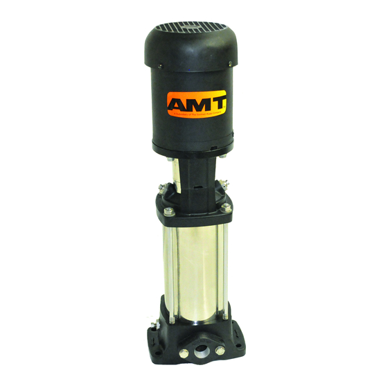
Preferred mounting position is with motor shaft aligned vertically.
(See Figure 1)
1.
Choose a solid, level surface with adequate support such as a concrete
slab floor.
2.
Use a level against pump to check for plumb. For uneven surfaces, shim
beneath feet of Casing (Ref. No. 38) to attain proper alignment.
3.
Securely fasten Casing to mount surface at all four mount holes to avoid
tip-over of pump. If space limitations dictate, pump may also be mounted
horizontally if adequate support is provided. Do NOT mount motor end
down or with shaft centerline below horizontal plane.
PIPING
Pump may have a protective cover over inlet and outlet for shipping purposes.
If present, be sure to remove these covers prior to attaching piping. If flange
5910-251-00
Screws (Ref. No. 41) are loosened, be sure to re-tighten evenly and torque to
33 ft-lbs [45 N-m] to avoid Gasket (Ref. No. 39) failure.
Starving the pump of liquid could cause low performance and damage to pump
and seal. To avoid this, use suction piping that is short and either matches
pump port diameter or is larger, do not reduce. Also, immediately preceding
pump inlet, provide a section of straight pipe equal in length to a minimum 4
diameters of pipe size and avoid using valves.
These pumps develop very high pressures. Be sure to confirm that pressure
rating of all piping and fittings is adequately sized before use. Rating must be
sufficiently larger than the combination of both inlet pressure plus the maximum
pressure pump can develop.
1
MSV1, MSV3 and MSV5 Series
Figure 1 - Mounting
10/2016
Advertisement

Related Manuals for AMT MSV3 Series


Summary of Contents for AMT MSV3 Series
- Page 1 Instructions. Failure to comply with the safety instructions accompanying this product could result in personal injury and/or property damage! Retain instructions for future reference. AMT reserves the right to discontinue any model or change specifications at any time without incurring any obligation.
-
Page 2: Operation
MSV1, MSV3 and MSV5 Series Specifications Information and Repair Parts Manual Multistage Centrifugal Pumps Piping and/or pipe fittings with an insufficient pressure rating may burst and cause personal injury and/or property damage. MAXIMUM INLET PRESSURE “1” Series 2 to 25 ..............335 ft./145 psi [1000 kPa] 27 stage .............. - Page 3 MSV1, MSV3 and MSV5 Series Specifications Information and Repair Parts Manual Multistage Centrifugal Pumps REASSEMBLY IMPORTANT: Pump Shaft may have been gouged from set screws. Before installing new Shaft Seal Assembly, smooth-over these gouges with a light grit emery cloth to prevent damage to new seal. Once shaft is free of burrs, lubricate Shaft and o-ring cavity in Adapter (Ref.
- Page 4 MSV1, MSV3 and MSV5 Series Specifications Information and Repair Parts Manual Multistage Centrifugal Pumps IMPORTANT: Stainless steel components deform easily, be careful to avoid Install wave Spring (Ref. No. 18) with ends pointed towards Adapter. With damaging pump components during disassembly. wave Spring seated on proper landing in Adapter, carefully guide Adapter Unscrew Hex Nut (Ref.
- Page 5 MSV1, MSV3 and MSV5 Series Specifications Information and Repair Parts Manual Multistage Centrifugal Pumps Problem Possible Cause(s) Corrective Action The pump does not run No power at motor. Check for voltage at motor terminal box. If no voltage at motor; check feeder panel for tripped circuits and reset.
- Page 6 MSV1, MSV3 and MSV5 Series Specifications Information and Repair Parts Manual Multistage Centrifugal Pumps Figure 5 - Assembly Map “1” & “3” Series 5910-251-00 10/2016...
- Page 7 MSV1, MSV3 and MSV5 Series Specifications Information and Repair Parts Manual Multistage Centrifugal Pumps Figure 6 - Assembly Map “5” Series 5910-251-00 10/2016...
- Page 8 MSV1, MSV3 and MSV5 Series Specifications Information and Repair Parts Manual Multistage Centrifugal Pumps For Repair Parts contact dealer where pump was purchased. Please provide following information: -Model Number -Serial Number (if any) Part description and number as shown in parts list Figure 7 - Repair Parts Illustrations 5910-251-00 10/2016...
-
Page 9: Repair Parts List
MSV1, MSV3 and MSV5 Series Specifications Information and Repair Parts Manual Repair Parts List Ref. Part Number for Models: Description “1” Series “3” Series “5” Series Qty. Motor See Page 9 See Page 9 See Page 10 5900-072-00 5900-072-00 5900-072-00 Coupling Incl. - Page 10 MSV1, MSV3 and MSV5 Series Specifications Information and Repair Parts Manual 5910-251-00 10/2016...
- Page 11 MSV1, MSV3 and MSV5 Series Specifications Information and Repair Parts Manual 5910-251-00 10/2016...
- Page 12 MSV1, MSV3 and MSV5 Series Specifications Information and Repair Parts Manual Figure 8 - Replacement Shaft Seal 5910-251-00 10/2016...
- Page 13 MSV1, MSV3 and MSV5 Series Specifications Information and Repair Parts Manual NOTES: 5910-251-00 10/2016...
- Page 14 MSV1, MSV3 and MSV5 Series Specifications Information and Repair Parts Manual NOTES: 5910-251-00 10/2016...
- Page 16 www.amtpump.com...
Need help?
Do you have a question about the MSV3 Series and is the answer not in the manual?
Questions and answers