Advertisement
Specifications Information and
Repair Parts Manual
Please read and save this Repair Parts Manual. Read this manual and the General Operating Instructions careful-
ly before attempting to assemble, install, operate or maintain the product described. Protect yourself and oth-
ers by observing all safety information. The Safety Instructions are contained in the General Operating
Instructions. Failure to comply with the safety instructions accompanying this product could result in personal
injury and/or property damage! Retain instructions for future reference.
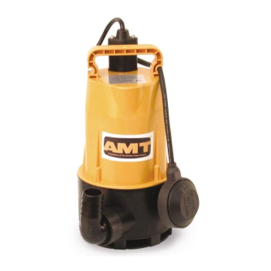
Submersible Pumps
Drainage / Sump Series
Refer to form 1808-636-00 for General Operating and Safety Instructions.
Description
These general purpose centrifugal Submersible Drainage /
Sump Pumps are intended for use in residential, commercial,
and industrial settings. Examples include: Basements, boats,
tanks, and other general drainage applications involving
clean liquids. Submersible design means low noise and no
priming issues.
Each unit is completely assembled and features a self-clean-
ing semi-open impeller and automatic on/off float switch
(stainless steel unit has no switch). All pumps incorporate a
mechanical shaft seal with carbon and ceramic wear faces.
Cast iron and SS pumps also feature a secondary shaft seal
and oil chamber.
Pumps have a 3450 RPM electric motor fitted with a finished
3-prong grounding type power cord. Motors are rated con-
tinuous duty and have automatic restart thermal overload
protection. Handle liquids from 40° to 104° F (4° to 40° C).
For use with clean, clear water and other non-flammable,
non-abrasive liquids compatible with pump component
materials.
Specifications
Discharge
Model
Outlet
HP
5800-99 1" HB
1/8
5810-99 1
1
/
HB
1/3
4
1
5811-99 1
/
HB
1/2
2
1
5790-95 1
/
NPT
1/3
2
5792-95 2 NPT
1/2
5780-98 2 NPT
1/2
NOTE: Driver data is subject to change without notice, see label on driver for actual specifications.
(HB) Male Hose Barb; (NPT) Standard NPT (female) pipe thread; (SS) 304 Stainless Steel
(*) With stainless steel, brass, and plastic components.
(**) With stainless steel, brass, plastic, and plated steel components.
(***) With stainless steel and plastic components.
Performance
Model
5800-99
5810-99
5811-99
5790-95
5792-95
5780-98
(†) Shutoff; to convert to psi, divide by 2.31
5780-250-00
Power Supply
Max.
@60 Hz
Amps
115VAC, 1 Phase
1.5
115VAC, 1 Phase
3.0
115VAC, 1 Phase
4.9
115VAC, 1 Phase
4.2
115VAC, 1 Phase
6.9
115VAC, 1 Phase
5.0
GPM of Water at Total Head in Feet
5'
10'
15
7
25
13
41
30
52
46
62
57
56
50
5780-98, 5790-95, 5792-95,
5800-99, 5810-99 and 5811-99
Cord
Basic
Impeller
Length
Const.
Material Seals
13'
Plastic*
Plastic
13
Plastic*
Plastic
13
Plastic*
Plastic
20
Cast Iron** Cast Iron Buna N 35
20
Cast Iron** Cast Iron Buna N 42
20
SS***
SS
15'
20'
—
—
—
—
18
3
40
31
50
42
43
34
Weight
(lbs.)
Buna N 11
Buna N 13
Buna N 15
Viton
26
Max.
25'
30'
Head†
—
—
14 ft.
—
—
14
—
—
21
18
—
30
34
22
37
21
6
32
03/2005
Advertisement
Table of Contents

Related Manuals for AMT 5790-95


Summary of Contents for AMT 5790-95
-
Page 1: Specifications
5780-98, 5790-95, 5792-95, Specifications Information and 5800-99, 5810-99 and 5811-99 Repair Parts Manual Please read and save this Repair Parts Manual. Read this manual and the General Operating Instructions careful- ly before attempting to assemble, install, operate or maintain the product described. Protect yourself and oth- ers by observing all safety information. - Page 2 5800-99, 5810-99 and 5811-99 Specifications Information and Repair Parts Manual Figure 1 - Dimensions Discharge Discharge Discharge Discharge Model 5810-99 & 5811-99 Model 5800-99 Model 5790-95 & 5792-95 Model 5780-98 Dimensions (Inches) W (Minimum Max. Model Discharge liquid height) solid 5800-99 1"...
-
Page 3: Maintenance
Specifications Information and Repair Parts Manual Models 5780-98, 5790-95, 5792-95, 5800-99, 5810-99 and 5811-99 Maintenance cord/float (Ref. No. 1) in next section. identical fashion. Make cer- IMPELLER REPLACEMENT tain that If unsure 5. Remove impeller fastener unit is disconnected from about (Ref. - Page 4 5780-98, 5790-95, 5792-95, Specifications Information and Repair Parts Manual 5800-99, 5810-99 and 5811-99 For Repair Parts, contact dealer where pump was purchased Please provide the following information: -Model number -Serial number (if any) -Part description and number as shown in parts list...
-
Page 5: Repair Parts List
5780-98, 5790-95, 5792-95, Specifications Information and Repair Parts Manual 5800-99, 5810-99 and 5811-99 Repair Parts List Part Number For Models:. Ref. 1-Inch - 1/8HP -Inch - 1/3HP -Inch - 1/2HP No. Description 5800-99 5810-99 5811-99 Qty. ~ Power cord/float kit... -
Page 6: Submersible Pumps
5780-98, 5790-95, 5792-95, Specifications Information and Repair Parts Manual 5800-99, 5810-99 and 5811-99 Submersible Pumps Drainage / Sump Series Maintenance components apart with place by pushing on it screwdriver. carefully with a piece of (Continued) pipe or dowel. Always 6. Press on end of motor promised.
Need help?
Do you have a question about the 5790-95 and is the answer not in the manual?
Questions and answers