Table of Contents
Advertisement
Quick Links
play.
2.
35 Default Modes.
3.
Modes can
CONNECTION DIAGRAM:
6
5
7
8
4
9
3
2
10
1
11
OVERALL DIMENSIONS:
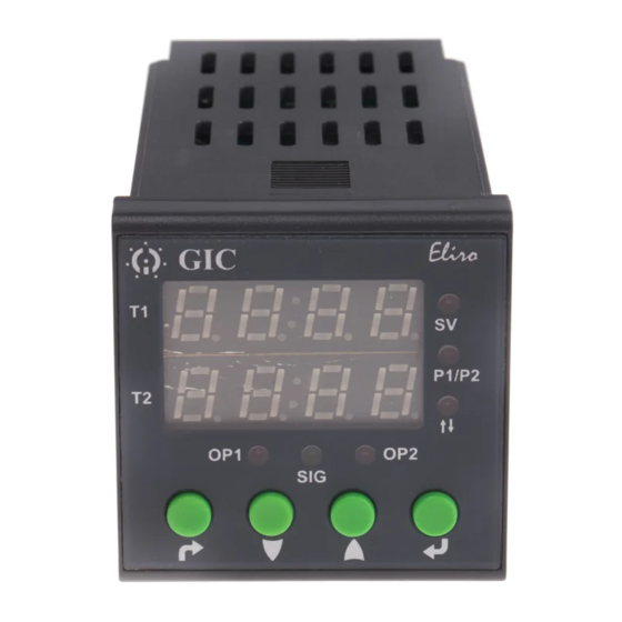
NOMENCLATURE FOR FRONT FACIA:
Key Conventions:
12.'UP' key short pressed in online edit mode - If both timers are configured then display
will show Set value of both the timers for 2 sec. When only one timer is configured then
it wil have no effect on the screen.
13.'Up/down' short pressed in Program mode - Increment/ Decrement the value/parameter.
14.'Down + UP' key long pressed in run mode when both timers are selected - Reset the
timer1 and timer2 both.
tmr2
Default Mode Configuration/Selection - User can select different
default Modes for Timer 1 and Timer 2. There are 35 inbuilt
default modes available.
Initial relay status before signal detection.
Configure the time for which Relay is required to be ON/OFF.
totL
Total time selection for Forward-Reverse Default Mode : 33.
Configure the time for which "Pause-Forward-Pause-Reverse"
cycle is required to be executed.
PSon
Pause-ON-Pause-OFF cyclic mode selection.
PSoF
Pause-OFF-Pause-ON cyclic mode selection.
FWd
Forward time (T1 On) Relay 1 selection.
rEv
Reverse time (T2 On) Relay 2 selection.
Number of ON/OFF Cycles i.e. user can select the two cycles with
different ON time & OFF time.
Break: If Break condition is selected in tdt1: ATT action is started,
there are four ATT actions Reload, Relay Off, New time and No.
Action will be taken after signal changes its state.If break is applied
no ATT is selected then toggle relay status and stop the cycle.
Action after time Completion, on opposite transition of signal or
level i.e. if cycles starts on SP then action for ATT is at SA.
Down or Remaining counting selection.
Enable or disable Semi-lock functionality. If semilock functionality
SLoC
is enabled then allow user to edit timings in RUN mode even if
the display is locked, by just pressing enter key for less than
three seconds.
User can configure the device (Timer 1 or Both Timers) in either Default Mode or
Customized Mode. Following are the examples of Operating Procedures to configure the
device in Default or Customized mode.
For Operating procedures of all 35 Defaults modes & Customized modes refer 'User
Manual' which can be downloaded from our website www.gicindia.com.
Example 1: IMPULSE ON ENERGIZING Select the Menu as given below to configure
the Timers for IMPULSE ON ENERGIZING (Default).
CnFb
both
ENTER
ESC
tmr1
dEFt
dEFt
16
ON time Scale
& time selection
tmr2
dEFt
dEFt
16
ON time Scale
& time selection
coUn
UP
SLoC
YES
selected).
PrFL
P1
Device configuration selection (tMr1 /both)-
Select 'BOTH' (Both Timers configuration).
Timer 1 mode selection
select Default.
Default mode number selection
Select 16.
Select the time scale & time for
which relay should remain ON.
Timer 2 mode selection
Select Default.
Default mode number selection
Select 16.
Select the time scale & time for
which relay should remain ON.
Time counting mode up/down
Select UP counting.
Enable or disable Semi-lock functionality
Select Yes.
At which profile number you want to save this profile
Select P1.
Example 2: SIGNAL ON/OFF DELAY TYPE (Refer Mode No. 13 on pageno. 02)
Select the Menu as given below to configure the Timers for SIGNAL ON/OFF TYPE 2
(Customized).
CnFb
Device configuration selection (tMr1 /both)- Select 'Timer 1'
tMr1
ENTER
ESC
Timer 1 mode selection (dEFt/CUSt)- select Customized
tmr1
CUSt
Customized mode selection(SIG/nSIG)- Select Signal based
CUSt
SIG
Initial output state before required signal state detection. E.g. this
IrLS
Mode/timer operation start at signal present, then here IrLS means
oFF
the Output state before signal presents.
Action to be taken on which signal transition (SP/SA)
SIG
Select Signal Present- Select SP- Level.
SP
Relay status after the transition of signal present (On/OFF)
rSP
Select Relay OFF.
OFF
Select the time scale & time for which relay should remain OFF
OFF time Scale
& time selection
Do you want to take action if the transition of signal occurs during
tdt1
Run time (YES/No) - Select Yes.
YES
Select transition on which you want to take any action (SA/SP)-
tdt1
Select Signal Absent.
SA
What Action do you want to take if the transition of signal absent
tdt1
occurs during timing (brEA/rLod/rEt/rLoF/PAUS)- Select Break
brEA
Select the action after above time completion on signal absent
Att
(no/rLoad/rLof/nEWt)- Select Reload
rlod
Do you want to take action if the transition of signal occurs during
tdt2
Run time after change in relay state (YES/no)- Select Yes
YES
Action to be taken on which signal transition (SA/SP)-
tdt2
Select SA - Signal Absent
SA
Do you want to take action if the transition of the signal absent
tdt2
occurs after change in relay state (PAUS/rLoD/rEt/rloF)-
PAUS
Select Pause
Do you want to repeat this cycle after every signal transition
rPtS
(YES/no) Select Yes.
YES
Counting method (UP/doWn)- here selected 'Down' as an example.
coUn
doWn
Enable or disable semi-lock functionality
SLoC
Select Yes.
YES
At which profile number you want to save this profile
PrFL
Select P1
P1
Example 3:
(Refer Mode No: 11 on page no 02
ASYMMETRIC CYCLE PULSE START
Select the menu as given below to configure the timers for ASYMMETRIC CYCLE
PULSE START (Customized) '
CnFb
Device configuration selection (tMr1 /both)- Select 'Timer 1'
tMr1
ENTER
ESC
Timer 1 mode selection (dEFt/CUSt)- select Customized
tmr1
CUSt
Customized mode selection(SIG/nSIG)- Select Signal based
Timer1 mode selection
CUSt
SIG
Initial output state before required signal state detection. E.g. this
IrLS
Mode/timer operation start at signal present, then here IrLS
oFF
means the Output state before signal presents.
Action to be taken on which signal transition (SP/SA)
SIG
Select Signal Present- Select SP- Level.
SP
Relay status after the transition of signal present (On/OFF)
rSP
Select Relay ON-OFF.
onof
Number of ON-OFF cycles (onE/tWo)- Select One.
CYCn
onE
Do you want to repeat the cycle (YES/no)- Select :Yes.
CYCr
YES
Select the time scale & time for which relay should remain in the
ON time Scale
ON state.
& time selection
Select the time scale & time for which relay should remain in the
OFF time Scale
& time selection
OFF state.
Do you want to take action if the transition of signal occurs during
tdt1
Run time (YES/No) - Select Yes.
YES
Select transition on which you want to take any action (SA/SP)-
tdt1
Select Signal Absent.
SA
During which relay status you want to take action if the transition
dUrn
of signal absent during run timing (on/oFF/both)- Select Both.
both
What action do you want to take if the transition of signal absent
tdt1
occurs during timing (brEA/rLod/rEt/rLoF/PAUS) - Select Relay OFF.
rLof
Do you want to repeat this cycle after every signal transition
rPtS
(YES/no) Select Yes.
YES
coUn
Counting method (UP/doWn)- here selected 'Down' as an example.
doWn
Enable or disable semi-lock functionality
SLoC
Select Yes.
YES
At which profile number you want to save this profile
PrFL
Select P2
P2
.
.
VLL010-05
Advertisement
Table of Contents

Related Manuals for GIC Eliro V7DDSS3 Eliro V7DFTS3


Summary of Contents for GIC Eliro V7DDSS3 Eliro V7DFTS3
- Page 1 Example 2: SIGNAL ON/OFF DELAY TYPE (Refer Mode No. 13 on pageno. 02) Select the Menu as given below to configure the Timers for SIGNAL ON/OFF TYPE 2 (Customized). CnFb Device configuration selection (tMr1 /both)- Select ‘Timer 1' play. tMr1 35 Default Modes.
- Page 2 Timing Diagram Operating Mode & Description Timing Diagram Operating Mode & Description PRODUCT SPECIFICATIONS: MODE - 19: ACCUMULATIVE DELAY ON INVERTED MODE - 00: ON DELAY Parameter Specifications SIGNAL On application of the supply voltage, the preset time Supply Characteristics: Time commences as supply voltage is applied and signal is duration (T) starts.
Need help?
Do you have a question about the Eliro V7DDSS3 Eliro V7DFTS3 and is the answer not in the manual?
Questions and answers