
Related Manuals for H2Scan HY-OPTIMA 2710


Summary of Contents for H2Scan HY-OPTIMA 2710
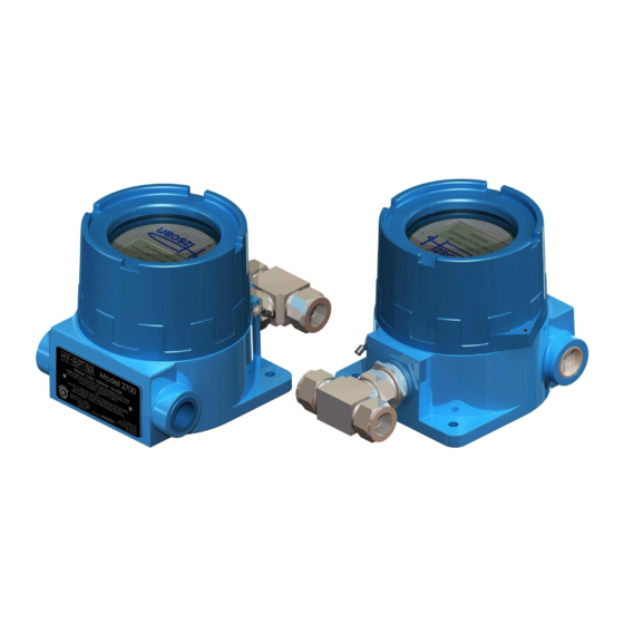
- Page 1 HY-OPTIMA™ 2700 Series ATEX Certified Explosion Proof In-line Hydrogen Process Analyzer OPERATING MANUAL...
- Page 2 Our Strategic Objectives H2scan's technology accepted as the new gold standard in hydrogen sensors. H2scan's business recognized for innovation and ingenuity, high quality products and systems, application - specific solutions, and exceptional customer service and satisfaction. H2scan's success results from teamwork, strategic partnerships and market leadership leading to sales growth and improved profitability.
-
Page 3: Table Of Contents
HY-OPTIMA™ 2700 Series ATEX Operating Manual Chapter 1: Model Specifications and Certifications Description ........................6 Models .......................... 6 1.2.1 Model 2710 ......................6 1.2.2 Model 2720 ......................6 1.2.3 Model 2730 ......................7 1.2.4 Model 2740 ......................7 Specifications ........................ 8 1.3.1 Performance Specifications .................. - Page 4 HY-OPTIMA™ 2700 Series ATEX Operating Manual 3.5.10 T Command (Data Log) ..................28 3.5.11 X Command (Clear Field Cal) ................29 3.5.12 F Command (Perform Field Cal) ................29 Display Menus ......................29 3.6.1 Intrinsically Safe Infrared Remote Control ............. 29 3.6.2 Intrinsically Safe Requirements ................
- Page 5 Product. Must Provide Notice of Defect: If you believe a Product that you believe is defective, you must notify H2scan in writing, within ten (10) days of receipt of such Product, of your claim regarding any such defect.
-
Page 6: Chapter 1: Model Specifications And Certifications
The H2scan thin film technology provides a direct hydrogen measurement that is not cross sensitive to other gases. The hydrogen specific solid-state sensing element is designed for ease of use, interface flexibility and true process control. -
Page 7: Model 2730
HY-OPTIMA™ 2720 Explosion Proof In-Line Process Hydrogen Analyzers operating in air do not require the conditioning procedure. H2scan recommends the hydrogen gas concentrations for both the Field Verification and Field Calibration gases to be 1% and 2% hydrogen in a balance of air. -
Page 8: Specifications
HY-OPTIMA™ 2700 Series ATEX Operating Manual 1.3 Specifications 1.3.1 Performance Specifications Hydrogen Hydrogen Accuracy Drift/ Week Repeatability Linearity Range MODEL MUST be Response Limit Limit Min to 10 to Min to 10 to Min to 10 to Min to 10 to present Time (sec) -
Page 9: Analyzer Certifications
The flameproof joints are not intended to be repaired; contact H2scan for information. The hydrogen sensor element inside the tube is not intended for repair, the assembly containing the sensor element may be replaced at an H2scan facility if it is defective; contact H2scan for information. 90000079 R8... -
Page 10: Dimensions
HY-OPTIMA™ 2700 Series ATEX Operating Manual 1.5 Dimensions (Units in inches) 90000079 R8 Page 10 of 45... -
Page 11: Chapter 2: Installation
For ambient temperatures below –10C use field wiring suitable for minimum ambient temperature. WARNING: H2scan’s HY-OPTIMA™ 2700 Series Explosion Proof In-line Hydrogen Process Analyzers are calibrated in a hydrogen/nitrogen (H2/N2) background and should NEVER be operated in an air or oxygen background unless using the 2720 model. - Page 12 HY-OPTIMA™ 2700 Series ATEX Operating Manual DO NOT unscrew these posts DO NOT unplug this cable Figure 1: Removing the Display Board If the cable is accidentally unplugged, plug it into the connector marked “INTF” (See Figure 2). Plugging it into any other connector will damage the Display Board and the Sensor Board.
-
Page 13: Wiring
HY-OPTIMA™ 2700 Series ATEX Operating Manual 2.2 Wiring All wiring is done on the Interface Board (Figure 3). The connectors are two piece designs in which the wires are screwed into a receptacle in standard terminal block style. This is plugged into the board. J4 Pin 1 J2 Pin 1 J5 Pin 1... - Page 14 HY-OPTIMA™ 2700 Series ATEX Operating Manual 1. Insert wires through the conduit connections. 2. Strip the insulation off the wires and make the connections to the connector block. 3. Plug the connector into the receptacle. 4. Pull any excess wire out of the enclosure. 90000079 R8 Page 14 of 45...
-
Page 15: Ac Power Wiring
HY-OPTIMA™ 2700 Series ATEX Operating Manual 2.2.1 AC Power Wiring Power Board: J2 4-Pin Terminal Block for the Power Cable Pin Number Function Description NEUTRAL Alternating current return LINE Hot AC power CHASSIS GROUND Safety connection to ground Common ground for sensitive circuitry isolated from chassis ground. If a SIGNAL GROUND signal ground is not available, short this pin with the chassis ground. -
Page 16: 4-20Ma Interface Wiring
HY-OPTIMA™ 2700 Series ATEX Operating Manual 2.2.4 4-20mA Interface Wiring Interface Board: J5 2-Pin Terminal Block for Output Cable Pin Number Function Description 4-20mA+ 4-20mA analog output 4-20mA - Hydrogen Level Power-On Self Diagnostic Error 4 mA to 20 mA 2 mA 3 mA 0 mA to 20 mA... -
Page 17: Analyzer Mounting
HY-OPTIMA™ 2700 Series ATEX Operating Manual 2.4 Analyzer Mounting Mounting is achieved with two ¼ inch diameter screws through mounting holes in the base of the explosion proof housing. ¾ inch solid conduit threaded into the enclosure will also serve as further structural support. Conduit unions are recommended on both sides of the analyzer to prevent damage to its threads in case a high torque is applied to the conduit. -
Page 18: Startup
HY-OPTIMA™ 2700 Series ATEX Operating Manual 2.5 Startup 2.5.1 Models 2710, 2730, 2740 If the analyzer is being turned on from an off position, power on the analyzer before flowing gas across the sensor. The sequence of steps which are to be followed is: Power on the analyzer and wait for the 5 minute warmup routine to complete. -
Page 19: Chapter 3: Operation And Configuration
HY-OPTIMA™ 2700 Series ATEX Operating Manual Chapter 3: Operation and Configuration 3.1 Optimum Analyzer Performance To maximize the performance of the analyzer: • Verify that all electrical connections are made as recommended. Switching the polarity can cause damage to the analyzer. •... -
Page 20: Pressure Sensor Installation
HY-OPTIMA™ 2700 Series ATEX Operating Manual 3.2.1 Pressure Sensor Installation Note: If using SB firmware older than 3.00, ensure a computer is available with a serial port and terminal software set up as this will be necessary to configure the analyzer. See Appendix B: Foxterm Setup for instructions. The pressure sensor can be placed before or after the analyzer in the process gas stream. - Page 21 HY-OPTIMA™ 2700 Series ATEX Operating Manual 2. From the Information Menu, scroll to the Pressure Menu by pressing the right button on the remote twice as follows: Display Pressure Sensor 1 Brighter Disabled Down: Norm;/Rev 3. To enable the pressure, press the middle button on the remote. This will open the configuration settings. Pressure Sensor 1 Enabled Low Volts:...
-
Page 22: Pressure Sensor Installation Troubleshooting
HY-OPTIMA™ 2700 Series ATEX Operating Manual 7. If using a pressure sensor with an absolute reading, set the PSI value to “PSIa.” If using a pressure sensor with a gauge reading, set the PSI vale to “PSIg.” The gauge setting will require a reference atmospheric pressure. -
Page 23: Serial Communication
Keystroke – This is the default mode which shows a continuous stream of output data until an ESC key is pressed. Then the H2scan prompt is displayed for the user to enter a command. After the command is finished the stream of output data continues. -
Page 24: A Command (Relays)
Append a user comment to the end of current line. Add a user comment line to the serial stream. Clear peak hydrogen value. Prompted Commands @ H2Scan prompt Command Description Enter the password to change security level. A null or invalid password returns to level 0. -
Page 25: Ci Command (Calibrate Analog Output)
3.5.3 CI Command (Calibrate Analog Output) Calibrate the Isolated DAC output range using a precision current meter and requires the level 2 password to be entered first (“=sensor”). Connect the current meter to the 4-20mA output and enter “ci” at the H2scan prompt as follows:... -
Page 26: H Command (Modify H2 Reporting Range)
G FFFF Display All Columns 3.5.6 H Command (Modify H2 Reporting Range) Modify the hydrogen reporting range. H2scan: h Hydrogen reporting range 0.0000-5.0000% H2 Enter new H2 low range: 1 Enter new H2 high range: 25 New Hydrogen reporting range 1 - 25% H2... -
Page 27: Ps Command (Configure Pressure Sensor)
The default value is 0.05. H2scan: ps External pressure sensor is disabled... -
Page 28: T Command (Data Log)
This allows access to the latest month of data. Additionally, any error events and power cycles are stored in the log. The parameters of the data log such as update interval and which values to store are configured at the factory. H2scan: t Trace Functions: c = clear log... -
Page 29: Command (Clear Field Cal)
3.5.11 X Command (Clear Field Cal) Clear the field calibration data. See Section 4.3.3 Clear Field Calibration (Restore Factory Calibration). To begin streaming data again, enter “G B5B8” at the “H2scan:” prompt or any other desired “G” command. Clear Field Calibration (Restore Factory Calibration). - Page 30 HY-OPTIMA™ 2700 Series ATEX Operating Manual R2 Level – level of hydrogen detected where second relay will actuate; Alarm level (standard factory setting: 2% hydrogen by volume) R3 – Select whether the Power Fail Indicator is enabled. Set H2 Range – Define hydrogen sensitivity range (standard factory setting: 0% to 100% hydrogen by volume) Low H2 Range –...
-
Page 31: Navigating The Display Menus
HY-OPTIMA™ 2700 Series Operating Manual 3.6.3 Navigating the Display Menus The display menus can be accessed by pressing the middle button on the remote control from the main screen shown below. 67.520% Aim the remote here Press ENTER to access menus The screen will now display the Information Menu. -
Page 32: Chapter 4: Field Calibration
(absolute), then the analyzer should be calibrated every three weeks. If there is not a specific desired tolerance, H2scan recommends the calibration be performed every three months. See Section 1.3.1 Performance Specifications to find the drift specification for a given model. -
Page 33: Calibration Procedure
HY-OPTIMA™ 2700 Series Operating Manual 4.3 Calibration Procedure Required materials: □ Two primary standard (±0.02%) calibration gases □ Flowmeter set to 1 slpm (~2 scfh) □ 30 minutes of time per gas (roughly 75 minutes total when including setup and gas switching) Only 20 minutes of time per gas is required for the 2720 □... - Page 34 HY-OPTIMA™ 2700 Series Operating Manual 3. Press the left arrow button on the remote to rotate to the Field Calibration menu: Field Calibration Last: 7/4/2016 Calibrate Sensor Clear Field Cal Change Avg (30) to select “Calibrate Sensor.” The calibration settings can 4.
- Page 35 HY-OPTIMA™ 2700 Series Operating Manual Enter the exact certification from the calibration bottles for highest accuracy. Verify all settings are set to the desired values and then press the right button on the remote to continue. : 2 Gases Apply 40.120%H2 Gas 1 : 40.120 %H2 Time 1: 30 min Gas 2 : 59.990 %H2...
-
Page 36: Procedure Using The Serial Interface
Taking Average… res=X.XXXX Calibration Gas #2 finished To begin streaming data again, enter “G B5B8” at the “H2scan:” prompt or any other desired “G” command. 4.3.3 Clear Field Calibration (Restore Factory Calibration) In the Field Calibration menu on the display, highlight “Clear Field Cal” and press the middle button on the remote control. -
Page 37: Chapter 5: Supplemental Information And Troubleshooting
HY-OPTIMA™ 2700 Series Operating Manual Chapter 5: Supplemental Information and Troubleshooting 5.1 Storage Note: Oxidation effects are not applicable to the model 2720 as it is designed to operate in air. 5.1.1 Storage Oxidation & Offsets Analyzer readings will develop an offset when the sensor element is not exposed to hydrogen. This offset accumulates slowly while the sensor is in storage, and quickly while the sensor is powered on without being exposed to hydrogen. -
Page 38: Avoiding A Storage Oxidation Offset
H2scan recommends this approach whenever it is feasible. For a fee, H2scan will keep a customer’s backup analyzers continuously powered on in hydrogen gas at our calibration facility, and ship out the fully conditioned backup sensor when it is needed. -
Page 39: General Troubleshooting
24 hours or until stability is observed. • Once the sensor is stable, perform a field calibration with two gases. • If the sensor does not stabilize, contact H2scan for support. 90000056 R8 Page 39 of 45... -
Page 40: Command Terminal Messages
Sometimes the error occurs because of a transient condition (“glitch”). If “htroff” is displayed, cycle the power to the analyzer. It should return to normal operation. If the error is permanent, the analyzer must be returned to H2scan for examination. Error_XXXX The following table lists possible errors and the code numbers that could appear on the display. -
Page 41: Connections
Enter then ESC. Verify the serial connections and FoxTerm Settings. No H2scan: Prompt: If pressing Enter then ESC does not show the H2scan: prompt, and FoxTerm is connected to the correct COM, port refer to the Section 5.5.6 Analyzer Command Line for further instructions. -
Page 42: Terminal Program
The analyzer is sending data to the serial port as measurements are made which is typically every second. Pressing the Enter then ESC keys should show the H2scan prompt. Sometimes the ESC key needs to be pressed twice to get the prompt. If the prompt is not displayed then press the following keys to establish... -
Page 43: Verify The Analog Output
HY-OPTIMA™ 2700 Series Operating Manual User configuration is: Hydrogen reporting range 0.0000-20.0000 %H2 Isolated Output is enabled: 4.000 to 20.000 mAmps Error output is 3.000 mAmps Not-Ready output is 2.000 mAmps In this example 4mA = 0ppm and 20mA=20%. This is an appropriate range if the hydrogen values of concern are between 0 and 20%. -
Page 44: Appendix A: Spare Parts
Connector terminal block 4 pos. , plug, 5.08mm, 180° 51000074* Connector terminal block 5 pos. , plug, 5.08mm, 180° 51000073* Connector terminal block 12 pos. , plug, 5.08mm, 180° 50000046* Intrinsically Safe Infrared Remote Control * Custom H2scan part 90000056 R8 Page 44 of 45... -
Page 45: Appendix B: Foxterm Setup
September 20th, 2011. The “.log” extension is the default, but any extension could be used. Newline Behavior must be set to “CRLF”. Click OK. Save the session as “H2scan.xml” in the FoxTerm program location. The setup should look similar to that shown. 90000056 R8...
Need help?
Do you have a question about the HY-OPTIMA 2710 and is the answer not in the manual?
Questions and answers