Table of Contents
Advertisement
Advertisement
Table of Contents

Related Manuals for COBHAM SAILOR 6560


Summary of Contents for COBHAM SAILOR 6560
- Page 1 SAILOR 65xx GNSS/DGNSS User manual...
- Page 3 SAILOR 65xx GNSS/DGNSS User manual Document number: 98-140657-A Release date: June 16, 2015...
- Page 4 In the event of any discrepancies, the English version shall be the governing text. Thrane & Thrane A/S is trading as Cobham SATCOM. Copyright © 2015 Thrane & Thrane A/S. All rights reserved.
- Page 5 Safety summary Observe the following general safety precautions during all phases of operation, service and repair of this equipment. Failure to comply with these precautions or with specific warnings elsewhere in this manual violates safety standards of design, manufacture and intended use of the equipment.
- Page 6 Preface Approvals The GNSS/DGNSS Receiver is approved to MED 2011/75/EU and fulfills the requirements in the standards: IEC 61108-1 Ed. 2.0, 2003 IEC 61108-2 Ed. 1.0, 1998 IEC 61108-4 Ed. 1.0, 2004 IEC 61162-1 Ed. 4.0, 2010 IEC 61162-2 1998 IEC 61162-450 2011 IEC 60945 Ed.
- Page 7 Related documents The following table shows the documents related to this manual and to the GNSS/DGNSS Receiver. Title and description Document number SAILOR 6588 GNSS/DGNSS Receiver, 98-145263 Installation manual SAILOR 6004 Control Panel, 98-136644 Installation manual SAILOR 6588 GNSS/DGNSS Receiver, 98-140656 Installation guide SAILOR 6286 DGNSS Antenna - Active,...
-
Page 9: Table Of Contents
Table of contents Chapter 1 Introduction Introduction to GNSS and DGNSS ..........1 Overview ........................1 The GNSS or DGNSS system ............2 System configuration .................... 4 System components ................4 SAILOR 6588 DGNSS Receiver ................. 4 SAILOR 6285 GNSS Antenna - Active ............5 SAILOR 6286 DGNSS Antenna - Active ............ - Page 10 Table of contents Chapter 3 Service & maintenance Maintenance ..................39 Contact for support .....................39 Service interface ....................40 System LEDs ......................42 Troubleshooting guide ..............43 Service and repair ................45 Applicable SAILOR part numbers ..............45 Accessories .......................46 To remove the cover ...................47 To replace the fuse ....................48 To repack for shipment ..................48 App.
-
Page 11: Chapter 1 Introduction
Chapter 1 Introduction This chapter introduces the GNSS/DGNSS Receiver and gives an overview of the system and services. It has the following sections: • Introduction to GNSS and DGNSS • The GNSS or DGNSS system • System components Introduction to GNSS and DGNSS Overview A GNSS receiver processes the signals transmitted by the satellites of Global Navigation Satellite Systems (GNSS). -
Page 12: The Gnss Or Dgnss System
Chapter 1: Introduction The GNSS or DGNSS system The GNSS/DGNSS Receiver is available in variants as listed in table 1. Depending on the antenna used the Receiver will either be a GNSS or a DGNSS Receiver. Using the SAILOR 6285 GNSS Antenna - Active gives a GNSS Receiver variant and the SAILOR 6286 DGNSS Antenna - Active gives a DGNSS Receiver variant. - Page 13 Control Variant Receiver antenna antenna Panel SAILOR 6560 GNSS System SAILOR 6561 GNSS Basic SAILOR 6570 DGNSS System SAILOR 6571 DGNSS Basic Table 1: System variants All variants include the DGNSS or GNSS App for the Control Panel. The application is an integrated part of the GNSS/DGNSS Receiver.
-
Page 14: System Configuration
Chapter 1: Introduction System configuration The following figure shows the units of a GNSS or DGNSS system. SAILOR 6285 SAILOR 6286 GNSS Antenna - Active DGNSS Antenna - Active SAILOR 6588 DGNSS Receiver SAILOR 6004 Control Panel TEST 6588 DGNSS Receiver 12-24 VDC 12-24 VDC Figure 1: System configuration... -
Page 15: Sailor 6285 Gnss Antenna - Active
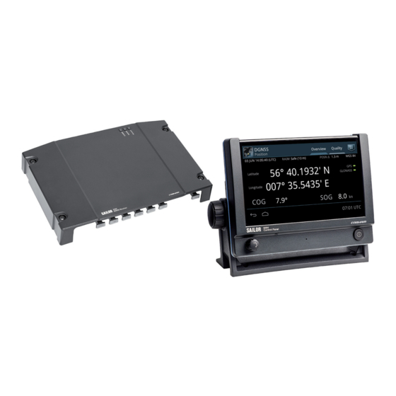
Chapter 1: Introduction Figure 2: SAILOR 6588 DGNSS Receiver SAILOR 6285 GNSS Antenna - Active The SAILOR 6285 GNSS Antenna - Active is a robust, sealed and waterproof GPS and GLONASS antenna (classified IPx6 & IPx8). Figure 3: SAILOR 6285 GNSS Antenna - Active System components... -
Page 16: Sailor 6286 Dgnss Antenna - Active
Chapter 1: Introduction SAILOR 6286 DGNSS Antenna - Active The SAILOR 6286 DGNSS Antenna - Active is a robust, sealed and waterproof GPS and GLONASS antenna. This antenna also has an antenna for receiving differential corrections from radio beacon stations in the LW frequency band. -
Page 17: Chapter 2 Operation
Chapter 2 Operation This chapter has the following sections: • To get started • Position • Anchor Watch • Trip Counters • Settings • Alert and notification management • List of alerts • Multiple receivers To get started As soon as DC power is provided the GNSS/DGNSS Receiver is on. To switch on the Control Panel push the power button. -
Page 18: Startup Screen
Chapter 2: Operation Startup screen The Control Panel is a multipurpose touch display on which the DGNSS or GNSS application has been installed during the installation of the GNSS/DGNSS Receiver. The startup screen provides an icon-based application menu including the DGNSS or GNSS application. To start the DGNSS or GNSS application tap the DGNSS or GNSS icon on the Control Panel display. - Page 19 Chapter 2: Operation Tap the back button to return to the previous screen/page of the current application or close the current application. If you tap this icon when being in the GNSS or DGNSS menu screen, you navigate to the startup screen. Hide keyboard button Tap the hide keyboard button to remove the on screen keyboard.
-
Page 20: Gnss/Dgnss Menu Screen
Chapter 2: Operation GNSS/DGNSS menu screen Tap the DGNSS or GNSS icon on the startup screen to display the menu screen. From this screen you access the main functions of the GNSS/DGNSS Receiver Figure 9: Menu screen (example for DGNSS) Tap Position, Anchor Watch, Trip Counters or Settings to proceed. -
Page 21: Position
Chapter 2: Operation Position The Position screen gives an overview of the current position and other relevant status information. This screen has the tabs Overview and Quality. Lists of GNSS satellites, SBAS satellites, beacons and beacon messages can be accessed through the icon in the upper right corner. When no position is calculated or the connection to the GNSS/DGNSS Receiver is lost, the position information in this screen is frozen and the text color is changed to yellow. - Page 22 Chapter 2: Operation accuracy, indicated in POSN field in the top information line. The estimated position accuracy is compared to the RAIM accuracy limit yielding the RAIM status. The RAIM accuracy limit is shown in parentheses. You can set the accuracy limit in DGNSS > Settings > Accuracy RAIM. Status Explanation Safe...
- Page 23 Chapter 2: Operation Figure 13: “LED” status section (example) Depending on the selected satellite system, the name of the system and an "LED" is listed in the LED status section. You can configure which systems to use in DGNSS > Settings > General > Use GNSS Systems. The name of the GNSS System may have a prefix, see the following table.
- Page 24 Chapter 2: Operation COG/SOG section This section displays the Course Over Ground (COG) and the Speed Over Ground (SOG). The COG and SOG are calculated together with the position and are only shown when the position is updated. COG is the average direction travelled in the time set by COG Smoothing (DGNSS >...
- Page 25 Chapter 2: Operation Figure 15: Quality of the position data When using SBAS corrections, Correction method shows SBAS and Correction reference shows the set SBAS correction system. You can set the SBAS Correction System in DGNSS > Settings > SBAS Correction System.
- Page 26 Chapter 2: Operation Lists of GNSS and SBAS satellites, beacons and beacon messages to display lists and details of the following: • GNSS satellites (GPS or GLONASS) • SBAS satellites • Beacons • Beacon messages In the list of SBAS satellites you can tap a satellite and display further details.
- Page 27 Chapter 2: Operation There are several ways to configure the beacon selection: > Automatic Mode to have the DGNSS Receiver • Tap automatically decide which beacon to use to achieve the most precise position. > Manual Mode to manually select the frequency and bit •...
- Page 28 Chapter 2: Operation Beacon indicator Explanation Current beacon. Automatically selected. Current beacon. Manually selected. Green dot Healthy beacon. Yellow dot Unhealthy beacon. Do not use under any circumstances. Gray dot Unmonitored beacon. Do not use unless no other station is available. Table 5: Beacon indicators 2.
-
Page 29: Anchor Watch
Chapter 2: Operation Anchor Watch The anchor watch feature informs you if the vessel has moved and has exceeded the intended anchoring position (Watch reference position). The GNSS/DGNSS Receiver will come up with an alert if the alert distance (Alert dist) is exceeded. - Page 30 Chapter 2: Operation Figure 21: Alert Distance for Anchor Watch (example) When Anchor Watch is active multiple indicators appear: The double circle indicates the position of the vessel (1), the cross in the middle indicates the Watch reference position (2) and the outer circle indicates the alert distance (3).
-
Page 31: Trip Counters
Chapter 2: Operation Trip Counters The GNSS/DGNSS Receiver has two trip counters and a total counter. The trip counters are updated when the system is switched on and a valid position is available. When the system is switched on, but there is no valid position, the travelled distance will be added to the counters when a position is obtained again. - Page 32 Chapter 2: Operation To see details about the trip, tap the trip counter of interest. Figure 24: Trip Counter (example) To reset a counter do as follows: 1. Tap the trip counter you want to reset. 2. Tap Reset and OK to confirm. Trip Counters...
-
Page 33: Settings
Chapter 2: Operation Settings If multiple Control Panels are connected to the GNSS/DGNSS Note Receiver the operator shall be aware of the possibility that complementary Control Panels may be operated simultaneously. The latest setting values in the GNSS/DGNSS Receiver are always synchronized to all Control Panels. -
Page 34: Settings - General
Chapter 2: Operation Settings – General General Description Use GNSS Select one of the following: Systems • GPS (default) • GLONASS • GPS / GLONASS SBAS Select one of the following: Correction • Disabled (no SBAS correction) (default) System • Automatic (Selects the most suitable correction system, see below) •... - Page 35 Chapter 2: Operation General Description Minimum Set the minimum satellite elevation above the horizon. Satellite Default value: 5 degrees Elevation Satellites with a low elevation may have a bad signal-to- noise ratio (SNR). Increase the elevation angle to exclude satellites with a low elevation angle. This reduces the number of satellites used to calculate the position which may therefore be less accurate.
- Page 36 Chapter 2: Operation General Description Adjustment of the responsiveness. Increase this setting to Smoothing avoid rapid fluctuations in SOG. The greater the smoothing value is set to, the longer will it take for the SOG to reflect changes in ship speed. Default: 5 s Zone Time Swipe to set the zone time.
- Page 37 Chapter 2: Operation To set a local Datum IHO Datum The local datums are implemented according to the "Users handbook on datum transformations involving WGS84", 3rd. edition from the International Hydrographic Organization. To set up an IHO datum do as follows: 1.
- Page 38 Chapter 2: Operation In some of the datums you must select a Subdivision. See an example in the next figure. Figure 27: Selection of a subdivision (example) 6. Tap Apply to use the datum for position calculation. User Defined If you want to use a local datum that is not in the list you can enter a user defined datum.
-
Page 39: Settings - Radio Beacons
Chapter 2: Operation 5. To display the valid range tap and hold the field. Figure 28: To display the valid range (example) Settings – Radio Beacons Radio Beacons Description Differential Select one of the following: Beacon • Enabled (default) Correction •... -
Page 40: Settings - Alerts
Chapter 2: Operation Settings – Alerts The following alerts can be set to enabled (default) or disabled in the GNSS/DGNSS Receiver: • HDOP Exceeded (password protected) • Loss of Position (password protected) • Differential Integrity Status (password protected) • RAIM Status - Unsafe •... -
Page 41: Alert And Notification Management
Chapter 2: Operation 4. Change the setting and tap Apply. When leaving Settings, it is locked again. For information how to change the user level password see the installation manual of the Control Panel. Alert and notification management Alert management is handled by the Control Panel. Note that the following description is a general description of alerts and notification. - Page 42 Chapter 2: Operation Icons for alerts and notification The following table shows the icons for alerts and notification with a description. Icon Name Icon description Active - A flashing red triangle. A symbol of a unacknowledged loudspeaker in the middle of the triangle. This alarm alert is accompanied by an audible alarm signal (3 beeps).
- Page 43 Chapter 2: Operation Icon Name Icon description Active - A flashing yellow circle with a symbol of a unacknowledged loudspeaker in the middle of the circle. This warning alert is accompanied by an audible warning signal (2 beeps). This icon is displayed when there is an active unacknowledged warning.
- Page 44 Chapter 2: Operation Alert history The alert history contains alerts of the last 24 hours (or maximum1000 entries).The alert history is cleared when you switch off the Control Panel. The alerts and notifications are not saved. To display the alert history with alerts and notifications do as follows 1.
-
Page 45: List Of Alerts
Chapter 2: Operation List of alerts The following alerts may be reported, depending on which alerts are enabled in DGNSS > Settings > Alerts. W: Warning C: Caution Alert Consequence Reason Remedy Anchor Distance from current position Relocate the Watch Alert to reference position vessel. - Page 46 Chapter 2: Operation Alert Consequence Reason Remedy HDOP Degraded HDOP has exceeded the user Improve GNSS Exceeded position defined threshold. reception accuracy. conditions. Bad reception Loss of No position fix. GNSS reception conditions are conditions can position (W) bad. be caused by The antenna has disconnected.
-
Page 47: Multiple Receivers
Chapter 2: Operation Multiple receivers The SAILOR 6588 DGNSS Receiver can be configured to act as primary, secondary or tertiary GNSS receiver, where each receiver can be controlled on the same SAILOR 6004 Control Panel. SAILOR 6588 DGNSS Receiver SAILOR 6004 Control Panel TEST 12-24VDC + 12-24VDC -... -
Page 48: Alerts And Notifications In A Multiple-Receiver System
Chapter 2: Operation 1 is the primary receiver. 2 is the secondary receiver. 3 is the tertiary receiver. Figure 32: Roles of the GNSS/DGNSS Receiver Tap the GNSS or DGNSS icon on the startup screen to display the menu screen for each receiver. Alerts and notifications in a multiple-receiver system Alerts and notifications are reported by icons in the bottom bar of the Control Panel, like in a stand-alone system with only one receiver. -
Page 49: Chapter 3 Service & Maintenance
Chapter 3 Service & maintenance This chapter has the following sections: • Maintenance • Troubleshooting guide • Service and repair Maintenance Maintenance of the GNSS/DGNSS Receiver and antennas can be reduced to a maintenance check at each visit of the service staff. Inspect the unit for mechanical damages, salt deposits, corrosion and any foreign material. -
Page 50: Service Interface
Chapter 3: Service & maintenance Service interface As long as the service engineer is logged into the Service Important Interface, the GNSS/DGNSS Receiver does not calculate positions. The Control Panel application shows a Connection lost error. All tasks related to installation, service and maintenance are described in the installation manual. - Page 51 Chapter 3: Service & maintenance 5. Tap Service Interface. Figure 35: Access the Service Interface and Login and enter user name 6. The service engineer can now tap and password (administrator level). Figure 36: Login page of the Service Interface Maintenance...
-
Page 52: System Leds
Chapter 3: Service & maintenance System LEDs Figure 37: LEDs on the GNSS/DGNSS Receiver Description Power Green: Power on. RAIM This LED indicates the quality of the position data. The RAIM accuracy in metres is set in the Control Panel. Green: The RAIM status is safe. -
Page 53: Troubleshooting Guide
Chapter 3: Service & maintenance Troubleshooting guide Problem Symptom Remedy The DGNSS The green power LED If the power cable is connected directly Receiver fails is off. to the GNSS/DGNSS Receiver then check to turn on. that the white wire in the power cable is connected to the black wire (-DC). - Page 54 Chapter 3: Service & maintenance Problem Symptom Remedy Check if Differential Beacon No beacon The (lower) beacon Correction/External RTCM correction status “LED” in the Overview screen is Correction (DGNSS/GNSS) is enabled in Settings > Radio Beacons. absent. The CORR LED on the receiver is lit and red.
-
Page 55: Service And Repair
Chapter 3: Service & maintenance Service and repair Should your Cobham SATCOM product fail, please contact your dealer or installer, or the nearest Cobham SATCOM partner. You will find the partner details on www.cobham.com/communications-and-connectivity/satcom where you also find the Cobham SATCOM Self Service Center web-portal, which may help you solve the problem. -
Page 56: Accessories
Chapter 3: Service & maintenance Accessories The following accessories are included in the delivery: Part number GNSS/DGNSS Receiver 37-207073-000 RJ45 Cat5e STP LAN cable, 5 m 67-138959 Accessory kit containing: 1 A fuse, fuse puller, mounting tool, cable tie, 5 screws M4x20 Torx A2, 5 screws ST ø3.9x33, T20 PAN head, self-tapping Table 13: Part numbers for included accessories (GNSS/DGNSS Receiver) Part number... -
Page 57: To Remove The Cover
Chapter 3: Service & maintenance To remove the cover To remove the cover, do as follows: 1. Loosen the 4 screws marked in the figure below. Figure 38: Removal of the cover 2. Remove the cables from the spring-loaded terminals and the connectors. -
Page 58: To Replace The Fuse
Chapter 3: Service & maintenance To replace the fuse One fuse (1 A) is installed in the GNSS/DGNSS Receiver. Figure 39: Location of the 1 A fuse If the fuse is blown, do as follows: 1. Track down why the fuse was blown and solve the problem, e.g. incorrect polarity at the DC supply. - Page 59 Chapter 3: Service & maintenance Correct shipment is the customer’s own responsibility. Note If the original shipping carton is not available, the following general instructions should be used for repacking with commercially available material. 1. Wrap the defective unit in heavy paper or plastic. Attach a tag indicating the type of service required, return address, part number and full serial number.
- Page 60 Chapter 3: Service & maintenance Service and repair...
-
Page 61: Sailor 6588 Gnss/Dgnss Receiver
Appendix A Specifications This appendix contains the technical specifications and a list of the supported NMEA sentences. SAILOR 6588 GNSS/DGNSS Receiver Item Specification GNSS receiver 30 channel GPS and GLONASS receiver Position-Fix time cold start 45 s PPS accuracy 15 ns Weight 1.3 kg Dimensions (L x W x H) -
Page 62: Sailor 6285 Gnss Antenna - Active
Appendix A: Specifications SAILOR 6285 GNSS Antenna - Active Item Specification Dimensions Ø: 91 mm, H: 77.5 mm Weight 0.15 kg Mounting Bracket mount on pipe, thread 1” x 14 TPI Equipment class Exposed, according to IEC 60945 Antenna type Active patch antenna Frequency 1570 to 1608 MHz... -
Page 63: Sailor 6286 Dgnss Antenna - Active
Appendix A: Specifications SAILOR 6286 DGNSS Antenna - Active Item Specification Dimensions Ø: 142 mm, H: 53 mm Weight 0.57 kg Mounting Bracket mount on pipe, thread 1 1/4” x 11 TPI Equipment class Exposed, according to IEC 60945 Antenna type Active patch antenna for GNSS combined with a H-Field antenna for beacons Frequency... -
Page 64: Sailor 6004 Control Panel
Appendix A: Specifications SAILOR 6004 Control Panel Item Specifications Mounting method Flush mount or bracket Voltage 10.8 to 31.2 VDC Power consumption Typical: 18 W active Peak: 42 W 3.15 A internal fuse (non-serviceable) Audio input Up to 6 W in 8 Ohm Interfaces 2 x Ethernet (10/100 Mbit/s) Accessories connector... -
Page 65: Nmea Sentences
Appendix A: Specifications NMEA sentences The following NMEA sentences are supported: Compliance Sentence IEC61108-1 For positioning reporting: DTM, GBS, GGA, GLL, GNS, GSV, RMC, VTG, ZDA IEC61108-4 For control and status reporting: MSK and MSS Heading sensor HDT, VHW, HDG, THS Alarm management ALR, ALC, ALF, ARC, ACN, ACK INS support Table 20: Supported NMEA sentences... - Page 66 Appendix A: Specifications NMEA sentences...
-
Page 67: Glossary
Glossary Glossary DGNSS Differential GNSS EGNOS European Geostationary Navigation Overlay Service GAGAN GPS And Geo Augmented Navigation, to improve the accuracy of a GNSS receiver by providing reference signals. GLONASS GLObal’naya NAvigatsionnaya Sputnikovaya Sistema. Global Navigation Satellite System in English. GNSS Global Navigation Satellite Systems General Public License... - Page 68 Glossary Local Area Network LGPL Lesser General Public License Long Wave MSAS Multi-functional Satellite Augmentation System. It supports differential GPS to supplement the GPS system by reporting on the reliability and accuracy of those signals. Minimum Shift Keying NMEA sentence for status information of beacon receivers NMEA National Marine Electronics Association (standard).
-
Page 69: Index
Index Index accessories, 46 Datum, 25 alarm, 31 datum alarms, 35 IHO, 27 alert distance user defined, 28 anchor watch, 19 datum parameter alerts, 31 valid range, 29 history, 34 DGNSS icons, 32 app, 8 multiple receivers, 38 software version, 39 settings, 30 dimensions, 54 anchor watch, 19... - Page 70 Index icon, 8 RAIM IHO datum accuracy, 24 set, 27 alerts, 30 LED, 42 RF exposure, iii Corr, 42 Power, 42 SBAS RAIM, 42 correction, 29 local datum, 28 satellites, 16 lock, 17 sensor inputs, 4 serial number, 39 Service Interface, 40 settings, 23 manual alerts, 30...
- Page 72 98-140657-A www.cobham.com/satcom...
Need help?
Do you have a question about the SAILOR 6560 and is the answer not in the manual?
Questions and answers