Table of Contents
Advertisement
Quick Links
Advertisement
Table of Contents

Subscribe to Our Youtube Channel
Related Manuals for Cumberland EXPERT WW


Summary of Contents for Cumberland EXPERT WW
- Page 1 EXPERT WW Temperature controller User’s Manual...
- Page 2 Every effort has been made to ensure that this manual is complete, accurate and up-to-date. The information con- tained in it is however subject to change without notice due to further developments. EXPERT WW rev.12...
-
Page 3: Table Of Contents
Static Pressure Set Points .......17 5.3. Temperature Curve .........18 ALARMS ............38 5.3.1. Principle of Operation ....... 18 11.1. Alarm Log .............38 5.3.2. Settings ..........18 11.2. Alarm Conditions ...........38 5.3.3. Modifying Curve Points ......18 11.3. Alarm Settings ..........39 EXPERT WW rev.12... - Page 4 14.2. Accessing the Transfer Menu ......43 14.3. Configuration Transfer ........43 14.3.1. Installing a New Configuration ....43 14.3.2. Saving a Configuration on the Card .... 43 14.4. Firmware Update ..........44 14.5. Erasing the Memory Card ........44 INDEX ...............45 EXPERT WW rev.12...
-
Page 5: Introduction
1. INTRODUCTION 1.2. Symbols of the Manual 1.3. Controller’s Overview Warning. Read the following text The EXPERT WW is an electronic device 1.1. Precautions carefully; it contains important used for environmental control in livestock information which, if ignored, may buildings. It combines sidewall and tunnel cause the controller to operate ventilation into one powerful system. -
Page 6: Main Features
Test Mode equipment. A test mode allows you to simulate tem- perature changes and verify controller per- formances. EXPERT WW rev.12... -
Page 7: Alarm Connection
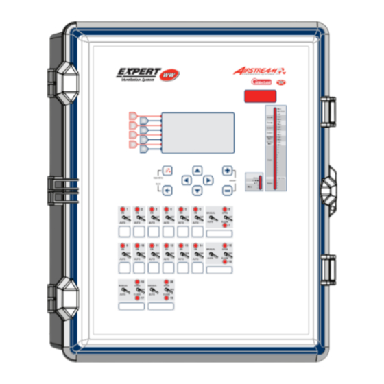
3.4 for further information about these LEDs. Backlight button — Press this button to light up the LCD screen. potentiometer fo r th e LC D contrast Page-up Page- down Back Navigation Adjustment buttons buttons Backlight Main menu button short-cut key EXPERT WW rev.12... -
Page 8: Parameter Adjustment
Hi or Lo fire heating step is on MISTING Solid LED: the misting output is active. COOL CELL Solid LED: the cool cell output is active. 0-10V OUTPUT Solid LED: 0-10V output #1 is active. CLOCK 1-2 Solid LED: clock output #x is active. EXPERT WW rev.12... -
Page 9: Installation Setup
0000 grams in use and to enable or disable the * A password may be required to access this menu. automatic program switch (section 4.5). 2. The password of all user levels are dis- played on screen. EXPERT WW rev.12... -
Page 10: Copying & Pasting Programs
(i.e., it is not selected as a function of the day transfer is over. and/or outside temperature). Select the run- ning program. *Only programs that are enabled in the Installation Setup are available (see sec. 4.5). The day number refers to the animal age. EXPERT WW rev.12... -
Page 11: Installation Setup
Use Heater Lo/Hi Fire? — Select “Yes” to acti- ates according to the static pressure level. is enabled above and it is common to all programs. vate the heating outputs’ Lo & Hi fire option. This function allows doubling the number of EXPERT WW rev.12... - Page 12 Use password? — Select “Yes” to enable the Misting — The controller can control one mist- password protection or “No” to disable it. ing output. Select “Yes” to enable this output. *[This parameter is common to all programs]. EXPERT WW rev.12...
-
Page 13: Rh Compensation Setup
Static pressure (SP) probe — Select “Yes” if levels are too high. Select “Yes” to use this from 1 to 100 gallons (or liters) per pulse. a static pressure sensor is connected to the compensation method. controller. EXPERT WW rev.12... -
Page 14: Probe Assignment
2. Select a relay then set its status as fol- are connected to these relays, their open and the end of this manual. lows: close relays can never be activated at the same time. EXPERT WW rev.12... -
Page 15: Assigning Min. Vent. Relays
Detect low temperature? — Select “Yes” to enable the low temperature alarm limit or select “No” to disable this alarm condition. EXPERT WW rev.12... -
Page 16: Test Mode
Test Mode — Switch on the test mode status and then set the simulated temperature to the desired value. The test automatically ends after 15 min- utes of inactivity. It can also end sooner by switching the test mode status back to “Off”. EXPERT WW rev.12... -
Page 17: Temperature & Set Point Settings
Installation 1. Select: Setup (sec. 4.5). Main menu Set Points 2. Set the following parameters: Static Pressure* Static pressure set points must be defined separately for each program of the controller. EXPERT WW rev.12... -
Page 18: Temperature Curve
Status — Select “Yes” to activate the curve. Once the curve is on, the controller auto- matically adjusts the set point automatically between consecutive points of the curve; for this reason, curve steps cannot be modified while the curve is running. EXPERT WW rev.12... -
Page 19: Ventilation & Cooling
“On Time” of minimum venti- lation cycles between consecutive points of a) The highest possible day number is 450. the curve; for this reason, curve steps cannot b) Decreasing day numbers is not allowed. be modified while the curve is running. EXPERT WW rev.12... -
Page 20: Fan Stages
(sec. 4.8), set the “On Time” the differential of stage 1 in section 6.2.3. and the “Off Time” of each timer-based relay. These “On & Off Times” can be adjusted from 0 to 15 minutes in increments of 15 seconds. EXPERT WW rev.12... -
Page 21: 0-10V Ventilation Outputs
Refer to the Clean Mode chapter of this manual for further information (see Stop at — This is the temperature below section 4.10) which the 0-10V output stops. EXPERT WW rev.12... -
Page 22: Natural Ventilation Curtains
Transition from natural to tunnel ventilation: When the natural ventilation curtain is opened and the room temperature reaches the start temperature of the first tunnel stage, the con- troller waits for the “Tunnel Close Delay” then fully closes the natural ventilation curtain. EXPERT WW rev.12... -
Page 23: Transition Between Natural & Tunnel Vent
Time” is common to both cycles). The open From natural to tunnel ventilation GRAPH 2 and close times range from 1 to 900 seconds From tunnel to natural ventilation (15 minutes); the “Off Time” ranges from 0 to 900 seconds (15 minutes). EXPERT WW rev.12... -
Page 24: Curtain Compensation
Compensation interval Current Outside T° Outside T Set Point Room T° Fan output Room T° The fans restart The curtain when the whisker reaches the switch is released. Whisker switch: the fans turn off. EXPERT WW rev.12... -
Page 25: Purge
It opens the doors when the pressure Wind Effect level exceeds the high pressure set point Delay and closes them when the pressure level is Time EXPERT WW rev.12... -
Page 26: Temperature-Based Tunnel Doors
#x Closed Fan stage #X Fan stage Room T° Set Point stage #X Start T° stage #X+1 Stop T° (first tunnel #X+1 Start T° stage) Stop T° EXPERT WW rev.12... -
Page 27: Tunnel Door Settings
Minimum age — Select the animal age below which both tunnel doors remain closed. Ad- justable from 1 to 450 days (or select Off to disable this function). *Available if age-based functions are enabled in the Installation Setup (section 4.5). EXPERT WW rev.12... -
Page 28: Vent Doors (Inlets)
Room T° at which vent doors (inlets) reach their over- Stage 1 Stage 2 Stage 3 Stage 4 Last Stage bandwidth starts starts starts starts starts opening position (Start T° of the last stage + over-opening bandwidth). EXPERT WW rev.12... -
Page 29: Actuator Reset
This the actuator (as defined in section 6.5.1.2). way, the vent door (inlet) never closes when the room temperature already asks for a wide EXPERT WW rev.12... -
Page 30: Potentiometer-Based Vent Doors (Inlets)
(inlet) closes according Stage 2 opening to the same cycle. Stage 1 opening Min.vent. opening Min Vent. Closed Over-opening Room T° Stage 1 Stage 2 Stage 3 Stage 4 Last Stage bandwidth starts starts starts starts starts EXPERT WW rev.12... -
Page 31: Vent Door Calibration
Wind the delay has elapsed. This way, vent doors Effect Delay (inlets) do not move if a wind draft causes Lo pressure limit fleeting changes in the pressure level. Wind Effect Delay Time EXPERT WW rev.12... -
Page 32: Vent Door Settings
Over Opening settings Opening 100 % Pre-opening Delay — Set the time that is Bandwidth 5.0 °F required to pre-open the vent door (inlet) before activating minimum ventilation fans. Adjustable from 0 to 120 seconds. to navigate EXPERT WW rev.12... -
Page 33: Cool Cell
LED is On: the cool cell output is on misting cycles: LED is Off: The mist output is off LED is On: The mist output is on EXPERT WW rev.12... -
Page 34: Heating
Heater 1 Lo fire On 73.0 °F Off 75.0 °F Hi fire On 72.0 °F Off 75.0 °F to navigate * A password may be required to access this menu. EXPERT WW rev.12... -
Page 35: Lights
Peak Intensity 100 % desired value (from 1 to 60 minutes). *This option is disabled above. Peak Sunrise 2 min parameter is accessible if the “lights on 24 hours” Peak Sunset 2 min option is disabled above. EXPERT WW rev.12... -
Page 36: Clock Outputs
** This menu is accessible if at least 1 clock output is enabled in the Installation Setup (section 4.5). On Time / Off Time or Run Time — Set the time at which each cycle starts then set the moment at which each cycle ends. EXPERT WW rev.12... -
Page 37: Relative Humidity (Rh) Compensation
Minimum & Maximum On Times — Set the minimum and maximum “On Times” of the heating timer. The minimum “On Time” starts being used when indoor humidity levels reach the RH set point; the maximum “On Time” is EXPERT WW rev.12... -
Page 38: Alarms
Outside Temperature + High opens in order to stop the feeder motor. This Alarm Offset (the offset being the difference alarm condition is optional. between the high alarm temperature setting and the set point). A third parameter, called EXPERT WW rev.12... -
Page 39: Alarm Settings
Critical temperature — Set the absolute temperature above which an alarm is set off. *This parameter is accessible if an outside tempera- ture probe is enabled (section 4.7.1). EXPERT WW rev.12... -
Page 40: Monitoring Functions
(section 4.5). Water Consumption — This menu contains the daily water consumption measured by each water meter for the past 75 days. *This parameter is accessible if at least one water meter is enabled in section 4.7.1. EXPERT WW rev.12... -
Page 41: Animal Age & Count
Installation Setup (section 4.5) current count. Please write down the meaning and the frequency of warning messages 1-3: MEANING FREQUENCY Warning 1 every ____days Warning 2 every ____days Warning 3 every ____days EXPERT WW rev.12... -
Page 42: Technical Specifications
Storage temperature ..........5 to 122 °F (-15 to 50 °C) Ambient relative humidity........max. 95% Pollution degree.............2 Altitude ..............Up to 2000m The relay strips of the RP-16, RP-32 and of the Expert WW control are not compatible and cannot be interchanged from one device to the other. EXPERT WW rev.12... -
Page 43: Memory Card
4. Select the desired transfer menu: Software (screen menus) User data (parameter settings) Main menu Memory Card Controller Pot. Calib (inlet calib. settings) 4. Once the transfer is over, press Exit then Controller Memory Card remove the memory card from the connector. EXPERT WW rev.12... -
Page 44: Firmware Update
FIRMWARE UPDATE File_name.cfg Select atm_0_7_30.bin atm_0_7_30.fir Exit 5. Press “Select” to get information about the selected firmware file (*.fir). FIRMWARE UPDATE Install this firmware? Name = Atm Advanced Version= x.y.zz ReleaseDate=2006-01-01 ModelVersion=0x111A EXPERT WW rev.12... -
Page 45: Index
Principle of operation 32 Fahrenheit units 10 Compensation Probe assignment 14 Fan stages Relative humidity comp.. See Relative humidity Settings 32 Activation 11 comp. Inputs Current fan stage in use 40 Connections 6, 7 Activation 13 Minimum ventilation. See Minimum ventilation Contrast (LCD screen) 7 List of available inputs 5 Principle of operation 20 Controller Installation setup 11–12 Relay assignment 14 Features 5 Installer password. See Password Settings 20 Firmware update 44 Timer relays Installation setup 11–12 Principle of operation 20 Location of the controls 7 Timer settings 20 Language selection 8 Mounting instructions 6 EXPERT WW rev.12... - Page 46 Posting # of mortalities 41 Activation 12 History 40 Mounting instructions 6 Principle of operation 20 Probe assignment 14 Relative humidity (RH) Probe set 2 - probe assignment 14 Inside RH sensor Probe set in use 40 Natural ventilation curtain Activation 13 Inside temperature probes Outside T° compensation 24 Calibration 13 Activation 13 Outside T° set point 17 Current reading 40 Current probe readings 40 Principle of operation 22 History 40 History 40 Probe assignment 14 Outside RH sensor Probe assignment 14 Purge cycles 25 Activation 13 Probe calibration 13 Settings 23 Calibration 13 Outside temperature Shutoff fans Current reading 40 Activation 13 Principle of operation 24 History 40 Current probe reading 40 EXPERT WW rev.12...
- Page 47 Principle of operation 25, 25–27 Probe set 2 27 Settings 27 Static pressure limits 17 Tunnel doors following natural curtains 11 Tunnel & Natural vent. transition 23 Tunnel doors (temperature-based) Activation 11 Principle of operation 25, 26–27 Probe set 2 27 Settings 27 Tunnel doors following natural curtains 11 Tunnel & Natural vent. transition 23 Units 10 User password. See Password Vent door/inlet (potentiometer) Activation 11 Calibration Loading an existing calibration 43 Operation & settings 31 Current position 40 Relay assignment 14 Settings 30 Vent door/inlet (pressure-based) Activation 11 Current position 40 Principle of operation 31 Relay assignment 14 Settings 32 Static pressure limits 17 Vent door/inlet (timer-based) Activation 11 Current position 40 Principle of operation 28–29 EXPERT WW rev.12...
Need help?
Do you have a question about the EXPERT WW and is the answer not in the manual?
Questions and answers