
Subscribe to Our Youtube Channel
Related Manuals for Igema FLB1


Summary of Contents for Igema FLB1
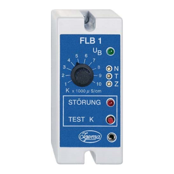
- Page 1 Conductivity limiter FLB1 for use with the level probes EL 18 or EL22 or EL23 D-08-B-39272-EN-0.doc Edition10/2017...
- Page 2 Measurement and control systems have been developed, produced and distributed worldwide for over 90 years under the IGEMA trademark. True to the motto “Steam is our passion”, we offer you a complete program for the safe and economical operation of your plant, in particular in the steam and condensate sector.
-
Page 3: Table Of Contents
3. Schematic diagram ..............................5 4. System description ..............................5 4.1 Application ................................ 5 4.2 Function ................................6 5. Design and installation FLB1 ..........................6 5.1 Installation dimensions and descriptions ....................6 5.2 Installation ................................ 7 5.3 Electrical connection ............................7 5.3.1 Wiring diagram ............................ -
Page 4: Risks And Safety Precautions
• Observe accident prevention regulations and system-specific safety instructions. • Only use the device supplied in accordance with the intended planning. • Do not add to or modify the device without the approval of IGEMA GmbH. Danger • Read and observe fitting and operating instructions. -
Page 5: Exclusion Of Liability
1.3 Exclusion of liability IGEMA GmbH Mess- und Regelsysteme will assume no liability if the above-mentioned regulations, instructions and safety precautions are not noted and followed. This symbol and signal word refer to a potentially hazardous situation which could result in death or injuries if ignored. -
Page 6: Contents Of The Packaging
4. System description 4.1 Application The TDS limiter FLB1 is used for continuous monitoring of the conductivity of liquids. The conductivity is measured using a measuring cell. This consists of a special conductivity electrode and tank wall or protective tube. -
Page 7: Function
Probes for use with the FLB1: Name Connection Feature Type EL18 32 bar 239°C G ½“ Piping-with flange mounting EL22 32 bar 239°C G ½“ frquently fitted with T-piece EL23 80 bar 296°C G ½“ protective tube installation 4.2 Function If a conducting liquid is in the measuring cell, the feeding triangular voltage drives a current through the liquid. -
Page 8: Installation
5.2 Installation Secure with protection class in accordance with current regulations Caution electrical voltage With top-hat DIN rail mounting for standard DIN46277 35 mm carrier rail • Snap the device on the standard carrier rail. • Loosen the fastening screws and remove the hood from the base. •... -
Page 9: Wiring Diagram
5.3.1 Wiring diagram Back plate Probe plug Safety chain Electrode rod ●... -
Page 10: Procedure
50 m. LIYCY min. 1.5 m² up to a max. length of 100 m (see note). Use a shielded cable for the current output (see note). • Only connect shielding on the FLB1 control unit (terminal 12). • After connecting to the power supply – with the device disconnected – place the hood on •... -
Page 11: Fitting The Probe
6 Fitting the probe It is essential to remove the cardboard protective tube for transport before installation! Caution If several probes are screwed into one flange, the probe plug and the associated probe should be labelled to prevent confusion! Screwing in the probe •... -
Page 12: El22
6.1 EL22 This probe is fitted horizontally into the boiler as standard using a T-piece. This enables the concentrated water, which is measured, to be directly discharged. In order to determine the length, note that there should be a free space of 40mm around the measuring tip. -
Page 13: El23
6.2 EL23 This probe is fitted as standard using a protective tube. -
Page 14: El18
6.3 EL18 This probe is fitted as standard using a flange in a pipe. With intermittent flow, a measurement can then be carried out and TDS reduction can be started. -
Page 15: Calibration
7. Adjustment Do not carry out adjustment until all the system components are installed. Switch on the mains voltage, the green warning light "U " lights up. Measuring instruments required for calibration: • Multimeter (preferably digital multimeter) Conductivity measuring device (preferably with temperature compensation) •... -
Page 16: Temperature Calibration
Press the "TEST K" key. If the circuit is interrupted at the terminals of the connection block (3 and 4), a fault in the FLB1 can be excluded. • Check the correct fitting of the conductivity electrode according to the operating instructions and the electrical connection according to the wiring diagram. -
Page 17: Limit Setting (Maximum Value)
Standards 12953-10 and 12952-12 contain requirements for the boiler water and the feedwater according to the permissible operating pressure. 8.1 Setting the FLB1 Set the desired limit value for maximum conductivity with the limit switch “K” taking into account the applicable directives. - Page 18 Fax.: +49 25 01 9 24 24 99 info@igema.com www.igema.com This high quality IGEMA product has been designed, manufactured and tested using the QM System specifications in accordance with DIN EN ISO 9001: 2000. If the device supplied shows transport damage or gives cause for complaint in spite of our final quality control please contact our SERVICE department by return.
Need help?
Do you have a question about the FLB1 and is the answer not in the manual?
Questions and answers