
Subscribe to Our Youtube Channel
Related Manuals for Igema AV250


Summary of Contents for Igema AV250
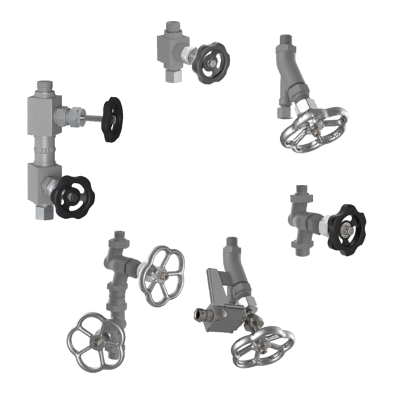
- Page 1 Drain valves Single and double drain valves Version: 01/2024 D-09-B-62825-EN-00 Installation and operating instructions (English translation)
-
Page 2: Table Of Contents
Optional versions ______________________________________________ 6 System Description General _____________________________________________________ 7 Function _____________________________________________________ 7 Construction AV250/ AV255 / AV320 _________________________________________ 8 AV500 / AV505/ AV520 / AV525 __________________________________ 9 AV540 / AV550 ______________________________________________ 10 AV580 / AV585 ______________________________________________ 10 AV251 _____________________________________________________ 10... - Page 3 Spindle / gland packing leaks ___________________________________ 24 Replacing packing ____________________________________________ 24 Spindle change ______________________________________________ 26 Seat change _________________________________________________ 27 Spare parts 10.1 AV250 / AV320/ AV251 ________________________________________ 28 10.2 AV500 / AV520 ______________________________________________ 29 10.3 AV540 / AV550 ______________________________________________ 29 Decommissioning and disposal 11.1...
-
Page 5: About This Document
If the gauge is passed on to a third party, these Installation and operating instructionsmust also be included in the national language of the third party. Safe and trouble-free operation of Igema GmbH Drain valves is not possible without precise knowledge. •... -
Page 6: Marking Of Safety And Warning Information
This operating manual contains texts and drawings that may not be reproduced, distributed or otherwise communicated in whole or in part without the express permission of the manufacturer. The copyright of the operating instructions remains with: Igema GmbH Antwerpener Str. 1 48163 Münster Germany Violations oblige you to pay compensation. -
Page 7: Safety Instructions
Only qualified persons who are familiar with the measurement and control systems are allowed to carry out work Igema GmbH can be commissioned for the installation and maintenance. AUTION Risk of injury due to external influences External influences can lead to injuries in the absence of protective equipment •... - Page 8 AFETY NSTRUCTIONS Risk of injury due to high temperatures Surfaces of the gauges and areas near the gauges heat up to the maximum permissible temperature and can cause severe burns if touched. • Check the danger of the medium. • Wear protective clothing including safety glasses.
-
Page 9: Intended Use
AFETY NSTRUCTIONS Risk of injury due to heavy loads There is a risk of injury when handling large and/or heavy gauges. • Observe the load handling regulation. • Use lifting equipment to move heavy and bulky appliances. 2.3 Intended use Property damage caused by irregular use •... -
Page 10: Contents Of The Packaging
ONTENTS OF THE PACKAGING 3 Contents of the packaging 3.1 Included In most cases, the valves are supplied as part of a gauge pre-assembled as a unit. Individual valves can also be supplied. 1. Valve in a pre-assembled unit or individual valve 2. -
Page 11: System Description
4 System Description 4.1 General IGEMA drain valves are largely maintenance-free and allow for easy handling. All IGEMA valves have metal seals; the valve spindle is sealed with a stuffing box packing. The shut-off valve designs range from a simple shut-off to a double shut-off. -
Page 12: Construction
ONSTRUCTION 5 Construction 5.1 AV250/ AV255 / AV320 AV250 / AV255 AV320 AV250 / AV255 AV320 Sealing ring Valve body Valve spindle Sealing ring Tension pin Packing set Stuffing box Valve upper part Cap nut Spindle guide Handwheel Washer Hexagon nut... -
Page 13: Av500 / Av505/ Av520 / Av525
ONSTRUCTION 5.2 AV500 / AV505/ AV520 / AV525 Example: AV500 Sealing ring Cap nut Valve seat Stuffing box Valve spindle Valve body Sealing ring Handwheel Scraper rings Open-close indicator disc Packing set Washer Valve upper part Hexagon nut D-09-B-62825-EN-00 Page / 9... -
Page 14: Av540 / Av550
AV525 with modified valve spindle and welded-on bracket with attached position switch. 5.5 AV251 The drain valve type AV251 is a double drain valve consisting of two AV250 type valves positioned one above the other. 5.6 AV560 / AV 570 The drain valve types AV560 and AV570 are double drain valves consisting of two AV540 or AV550 valves positioned one above the other. -
Page 15: Technical Data
ECHNICAL DATA 6 Technical data 6.1 Limitations of use Application limits AV250 / AV251 Pressure / temperature assignment PN250 according to EN12516-1 Class 1500 according to ASME B16.34 Application limits AV320 Pressure / temperature assignment PN320 according to EN12516-1 Class 2500 according to ASME B16.34... -
Page 16: Dimensions
Drawings of the valves with specified connections are shown and dimensioned below. Customised connections are possible and have an effect on the connection dimensions and absolute lengths. AV250/ AV255 / AV320 Example: AV250 with cutting ring fitting DS12 Example: AV320 with cutting ring fitting DS12 AV250/ AV255 AV320... - Page 17 ECHNICAL DATA AV500 / AV505/ AV520 / AV525 AV500 / AV505 AV520 / AV525 [mm] [inch] [mm] [inch] Absolute length Connection dimension Width Handwheel [Ø diameter AV540/ AV545/ AV550 / AV555 [mm] [inch] up to 32 bar/ 464 psig (AV540/ AV545) Handwheel [Ø] diameter...
- Page 18 ECHNICAL DATA AV580/ AV585 AV580 AV585 [mm] [inch] [mm] [inch] Absolute length ~240 ~240 Connection dimension Width ~145 ~145 Handwheel diameter [Ø AV560 / AV565 / AV570 / AV575 AV560 / AV565 AV570 / AV575 [mm] [inch] [mm] [inch] Connection thread "...
- Page 19 ECHNICAL DATA AV251 [mm] [inch] Connection thread " BSP Diameter Connection diameter [D1] Handwheel diameter [D2] Height Connection height [h1] Width across flats [SW] ◻35 ◻1 Square measure Connection length [L1] Total length D-09-B-62825-EN-00 Page / 15...
-
Page 20: Position Switch For Av580 / Av585
ECHNICAL DATA Position switch for AV580 / AV585 • Powder-coated die-cast aluminium housing • Snap action, changeover contact with double break • Cable gland with clamping jaws M16x1.5mm, nickel-plated • Plunger actuator with recessed stainless steel ball IP65 Protection class according to IEC/EN 60529 1 opener, 1 closer Switching elements max. -
Page 21: Assembly
SSEMBLY 7 Assembly 7.1 Version with flange • Observe the orientation of the gauge . • Check sealing surfaces for cleanliness • Assemble the flange connection between the gauge and the valve in accordance with the applicable standard 7.2 Version with welding sleeve ARNING Eye damage due to lack of personal protective equipment Lack of eye protection during welding leads to eye damage in working and bystanders. -
Page 22: Threaded Version
SSEMBLY 7.3 Threaded version Fig.1 Figure 1: • Screw the drain valve with seal into the gauge body with a torque of 120 Nm. 7.4 Drain tubing Fig.1 Figure 1: • Mount tube Ø12x1mm (made of material P235GH) on site to the screw connection provided according to DIN 2353 (SW24) NVIRONMENT Danger to the environment due to escaping medium... -
Page 23: Commissioning
OMMISSIONING 8 Commissioning ARNING Risk of injury due to leaking medium Inflammatory, irritating and harmful substances can escape from the gauge and lead to skin injuries and burns. This danger is also to be expected in the case of an unpressurised cooled system. -
Page 24: Commissioning At The Same Time As The Boiler
OMMISSIONING 8.2 Commissioning at the same time as the boiler This type of commissioning is recommended by Igema GmbH due to the lower stress on the components. Commissioning at the same time as the boiler must be carried out in the same way for all gauge types. -
Page 25: Case Of Damage
Replaced spare parts that do not correspond to the characteristics of the original spare parts may cause damage to the gauge. • Only use original parts from Igema GmbH for replacement. Material damage due to insufficient or incorrect lubrication Lubrication of components with inadequate or incompatible lubricants can lead to material damage. - Page 26 Carry out work as • Material settings described in (Chap. 7.4 Fig. • Wear and tear • Insufficient torque on screw connection Permanent damage to valve type Wear and tear Replace valve (chap. 0) AV250, AV251, Av255, AV320 Damage Page / 22 D-09-B-62825-EN-00...
-
Page 27: Replacing The Drain Valve
ASE OF DAMAGE 9.1 Replacing the drain valve Fig.1 Fig.2 Fig.3 Fig.4 Figure 1: • Unscrew the pipework fitting from the drain valve • Pull off pipework Valves and gauges that are firmly connected to each other (e.g. welded connections) must be separated from each other at the connection points. For this purpose, suitable tools must be selected according to the application and environment. -
Page 28: Spindle / Gland Packing Leaks
ASE OF DAMAGE 9.2 Spindle / gland packing leaks Fig.1 Fig.2 Figure 1: • Tighten the union nut with a hexagon spanner Figure 2: • Open the drain valve 2-3 times. 9.3 Replacing packing Fig.1 Fig.2 Fig.3 Fig.4 Fig.5 Page / 24 D-09-B-62825-EN-00... - Page 29 ASE OF DAMAGE Fig.6 Fig.7 Fig.8 Fig.9 Fig.10 Fig.11 Figure 1: • Loosen the hexagon nut with an SW13 hexagon spanner. • Remove the washer, indicator disc and handwheel from the spindle. Figure 2: • Unscrew the valve upper part with installed parts from the valve body using an SW32 hexagon spanner.
-
Page 30: Spindle Change
ASE OF DAMAGE Figure 6: • Grease the valve spindle and screw it into the valve upper part from below. Figure 7: • Grease the new packing set and insert with wiper rings. • Insert stuffing box. Figure 8: • Screw the union nut onto the valve upper part. Figure 9: •... -
Page 31: Seat Change
ASE OF DAMAGE Seat change Fig.1 Fig.2 ▪ Follow these steps after unscrewing the complete valve upper part (chap. 9.3, fig. 1-2) Figure 1: • Screw the valve spindle downwards out of the upper part of the valve. Figure 2: •... -
Page 32: Spare Parts
Only use original parts from Igema GmbH for replacement. 10.1 AV250 / AV320/ AV251 If the drain valves of type AV250, AV251 or AV320 are damaged, the entire valve must be replaced. If the drain valve is dismantled for maintenance or other reasons, check the thread for damage before dismantling, apply a suitable lubricant (e.g. -
Page 33: Av500 / Av520
PARE PARTS 10.2 AV500 / AV520 Pos. Item Quantity Item numbers Sealing ring 40-00099 ø 21 x 26 x 1,5 mm 40-01864 Seat 40-01866 Spindle with cone Sealing ring 40-01873 ø 24 x ø 19.5 x 1 40-01867 Packing set 40-02360 Scraper rings Spare parts package... -
Page 34: Decommissioning And Disposal
ECOMMISSIONING AND DISPOSAL 11 Decommissioning and disposal 11.1 Dismantle valve Flange connections During the following work, the individual components hang freely and must be secured against falling. • Loosen nuts on flange connections. • Removing bolts from flanges • Secure the seal between the flanges against falling off Fig.1 Fixed connections... -
Page 35: Disposal
Residues of hazardous substances pose a health hazard. • Indicate possible dangers and take precautionary measures. This high-quality IGEMA product was designed, manufactured and tested with the application of the QM System guidelines in accordance with DIN EN ISO 9001:2015. - Page 40 Direct Download Product page on the Internet Igema GmbH Antwerpener Str. 1 Phone: +49 2501 924 24 0 Fax: +49 2501 924 24 99 48163 Münster Germany info@igema.com www.igema.com...
Need help?
Do you have a question about the AV250 and is the answer not in the manual?
Questions and answers