Table of Contents

Related Manuals for Baker Instrument Company PP24


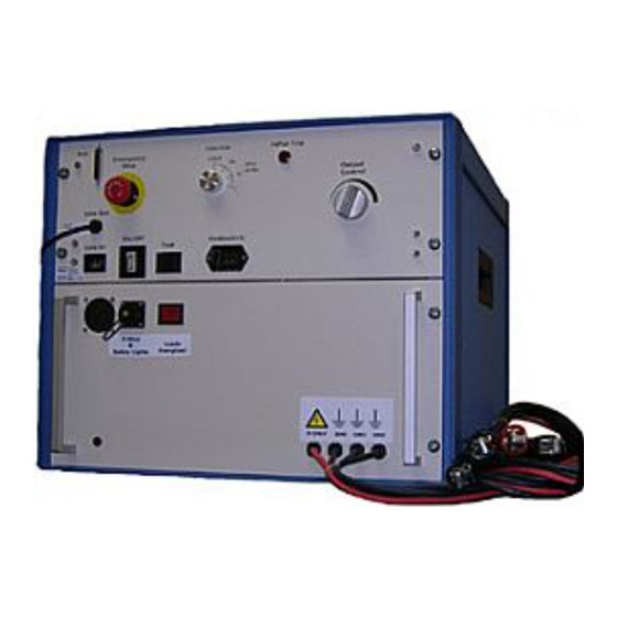
Summary of Contents for Baker Instrument Company PP24
- Page 1 User’s Manual DC HiPot/Surge Tester (Power Pack) Model PP24 Baker Instrument Company, an SKF Group Company 4812 McMurry Avenue Fort Collins, CO 80525 (970) 282-1200 (970) 282-1010 FAX (800) 752-8272 USA Only 12/7/2009 | 71-026 V2 PP24...
-
Page 2: Warranties; Disclaimers
Warning: Baker Instrument Company, an SKF Group Company assumes no liability for damages consequent to the use of this product. No part of this document may be reproduced in part or in full by any means such as photocopying, photographs, electronic recording, videotaping, facsimile, etc., without written permission from Baker Instrument Company, an... -
Page 3: Table Of Contents
Shipment ............................8 1 ......................... 11 Getting started ....................11 ........................11 ENERAL NFORMATION How Does the PP24 Work?......................11 Recommended Test Voltages ....................12 2 ......................... 13 DC testing/DR unit....................13 Other Important Safety warnings ....................13 DR DC Tests Operation ......................14 Megohm/PI/HiPot testing......................15... - Page 4 Table of Contents 5 ......................... 33 Surge Testing/AWA....................33 Other Important Safety warnings ....................33 PP24................... 34 URGE ESTING WITH THE Performing Complete Motors Tests with the AWA..............36 Index ........................37 12/7/2009 | 71-026 V2 PP24...
-
Page 5: Preface
Specific warnings and cautions will be found throughout this manual where they apply. Note: If the equipment is used in any manner not specified by Baker Instrument Company, an SKF Group Company, the protection provided by the equipment may be impaired. -
Page 6: Power Source Precautions
Do not change the Test Lead Select, if so equipped, switch setting during a test. − When increasing the applied voltage, switch to a higher Volts/Div setting so the entire wave pattern remains visible on the display. 12/7/2009 | 71-026 V2 PP24... -
Page 7: Symbols On Equipment
The unit is intended for use in Installation Category II (Portable Equipment) areas and pollution Degree II Environments where occasional non-conducting condensing pollution can be encountered. Unpacking the unit Carefully remove the following items from the shipping boxes. ST103A, ST106A or ST112A Power cord 12/7/2009 | 71-026 V2 PP24... -
Page 8: Power And Utility
Foot Switch The PP24 comes with a foot switch that plugs into the front panel of the instrument. This foot switch takes the place of the Test button on the unit’s front panel. Often, it is convenient to use the foot switch especially when making PI measurements. - Page 9 EN 61000-4-3 EN 61000-4-5 EN 61000-4-5 EN 61000-4-6 EN 61000-4-11 I, the undersigned, hereby declare that the equipment specified above conforms to the above Directives and Standards. Signature: Printed Name: Mike Teska Title: Engineering Manager. 12/7/2009 | 71-026 V2 PP24...
- Page 10 Safety Warnings and Notices 12/7/2009 | 71-026 V2 PP24...
-
Page 11: Getting Started
The PP24 is ideal for testing large 4kV and 7kV class windings. The PP24 cannot operate alone - a Baker AWA or DR host tester is required to operate the PP24. The host has the brains to control the PP24 and can save the test data taken with the PP24. -
Page 12: Recommended Test Voltages
PP24 test. The test leads for the host unit should be coiled up and placed on top of the host so that the host and PP24 test leads are separated and not confused with each other. -
Page 13: Dc Testing/Dr Unit
Ground the product : This product is grounded through the grounding conductor of the power cord. To avoid electrical shock, plug the power cord into a properly wired/grounded receptacle before connecting the product test leads. 12/7/2009 | 71-026 V2 PP24... -
Page 14: Dr Dc Tests Operation
Place the DR unit on top of the PP24 and connect the interface cable to the two units. Coil up the DR’s test leads and place them on top of the DR. -
Page 15: Megohm/Pi/Hipot Testing
Observe on the screen, record and save the test results to the tester. Megohm/PI/HiPot testing Before going into the DC tests with the PP24, it must be noted that the PP24 may require a voltage regulator to stabilize the incoming power to the unit. If the incoming AC is not well regulated, the output voltage of the PP24 will change along with any changes in the incoming AC power. - Page 16 DC Testing/DR Unit PP24. Also, very accurate Megohm and PI measurements can be made with the DR which has a very tightly regulated high voltage power supply regardless of the quality of the incoming power. To perform Megohm/PI/HiPot testing with the PP24, ensure the two units are connected &...
- Page 17 DC Testing/DR Unit turn the output control knob so fast that the PP24 HiPot trips while charging the motor’s ground wall capacitance. Once the test voltage is reached, stop turning up the output control knob, set the time to zero by pressing the T=0 button on the DR, and follow the instructions on the DR’s display on changing the current range to the most sensitive range.
- Page 18 PI test has elapsed. At 10 minutes, the readings for the PI test will automatically be recorded. If a HiPot test is desired, keep the Test button depressed, change the PP24’s function knob to the 100uA/div (as shown below) and raise the output voltage to the required HiPot test voltage.
- Page 19 DC Testing/DR Unit Fig 5-10: At DC test completion 12) Release the Test button and allow the voltage on the PP24’s test leads to drop to zero before touching the test leads. Fig 2-11: Storage Screen 13) To save the data just recorded, press the Store button on the DR and select a record to save the data to.
- Page 20 DC Testing/DR Unit 12/7/2009 | 71-026 V2 PP24...
-
Page 21: Surge Testing/Dr Unit
Upon completion of a DC High Potential, Megohm, Polarization Index, Dielectric absorption, before disconnecting the test leads, short the winding, motor, etc., to ground 12/7/2009 | 71-026 V2 PP24... -
Page 22: Surge
Surge Testing with the PP24 and DR Surge testing a three phase AC induction motor with the DR and a PP24 is done one lead at a time. The PP24’s test leads are arranged as follows: For testing Lead 1 / Phase A: −... - Page 23 The details of performing a surge test will now be described (this discussion assumes both the DR and PP24 are connected and powered up as described at the beginning of this chapter): Turn the Function knob on the PP24 to the surge position.
- Page 24 Volts per Division knob to the next higher position. (A message will be displayed on the screen instructing the operator to increase the V/div setting.) Fig 3-4: Division settings 12/7/2009 | 71-026 V2 PP24...
- Page 25 11) Once the target test voltage is reached, release the test button. 12) Set the PP24 output control knob to min to set the test lead voltage to zero. Fig 3-5: Store screen - Surge 13) Save the waveform by pressing the Store button on the DR and selecting a record to save the data.
-
Page 26: Printing A Report
Recall button, selecting the record to be printed and pressing the Summary button. The Error Area Ratio (EAR) is a calculation that gives a quantitative measure of the difference of two waveforms. Mathematically the formula is 12/7/2009 | 71-026 V2 PP24... - Page 27 The EAR algorithm is on the DR to calculate the Line to Line EAR (L-L EAR). The L-L EAR is used to numerically quantify the difference between the three waveforms of a three phase motor’s surge test. Fig 3-7: Graphical EAR explanation 12/7/2009 | 71-026 V2 PP24...
- Page 28 Surge Testing DR Unit 12/7/2009 | 71-026 V2 PP24...
-
Page 29: Testing With A Awa Unit
18) Ground the product : This product is grounded through the grounding conductor of the power cord. To avoid electrical shock, plug the power cord into a properly wired/grounded receptacle before connecting the product test leads. 12/7/2009 | 71-026 V2 PP24... -
Page 30: Dc Testing With An Awa
Place the AWA unit on top of the PP24 and connect the interface cable to the two units. Coil up the AWA’s test leads and place them on top of the AWA. -
Page 31: Megohm/Pi/Hipot Testing
AWA. Megohm/PI/Hipot Testing Before going into the DC tests with the PP24, it must be noted that the PP24 may require a voltage regulator to stabilize the incoming power to the unit. If the incoming AC is not well regulated, the output voltage of the PP24 will change along with any changes in the incoming AC power. - Page 32 If and when the charging current drops below 8-9uA, move the Function knob to the 11uA/div position. 10) At the end of the test, the AWA will automatically shutdown the PP24. A Discharge Bar will appear on the AWA screen. Wait until the Discharge Bar disappears before moving or touching the test leads.
-
Page 33: Surge Testing/Awa
Use appropriate safety equipment required by your organization, including high voltage globes and eye protection. Repair Parts Warning : Defective, damaged, or broken test leads must be replaced with factory-authorized parts to ensure safe operation and maintain performance specifications. 12/7/2009 | 71-026 V2 PP24... -
Page 34: Surge Testing With The Awa And Pp24
Surge Testing with the AWA and PP24 Surge testing a three phase AC induction motor with the AWA and a PP24 is done one lead at a time. The PP24’s test leads are arranged as follows: Fig 5-1: Lead connections For testing Lead 1 / Phase A: −... - Page 35 The details of performing a surge test will now be described (this discussion assumes both the AWA and PP24 are connected and powered up as described at the beginning of this chapter): Fig 5-3: Function knob PP24 Turn the Function knob on the PP24 to the surge position.
-
Page 36: Performing Complete Motors Tests With The Awa
If the Megohm / PI test has been selected, the software will again direct the operator to connect the appropriate host test leads. If the PP24 is to do the Hipot test, the software will direct the operator to disconnect the AWA’s test leads, and hook up the PP24’s test leads. -
Page 37: Index
Safety · 8, 9 Surge · 9, 11, 15, 21, 22, 24, 26, 33, 34, 36 HiPot · 1, 12, 15, 16, 17, 18, 26, 31 Tests Operation · 14 Megohm · 15, 16, 17, 31, 36 12/7/2009 | 71-026 V2 PP24... - Page 38 Index 12/7/2009 | 71-026 V2 PP24...
Need help?
Do you have a question about the PP24 and is the answer not in the manual?
Questions and answers