
Related Manuals for Böhnke + Partner bp308

Summary of Contents for Böhnke + Partner bp308
- Page 1 Installation Manual System »bp308« General Information Safety instructions Commissioning EC-Type Examination www.boehnkepartner.de...
- Page 2 Regardless of the care that has been used for the creation of text, illustrations, and pro- grams, we can not take responsibility for possible errors or the consequences of a legal liab- ility. Installation Manual System »bp308« The data presented in this work, names, trade names, trademarks, etc., may be trademarks February 2014 and are subject to statutory provisions even if not explicitly.
-
Page 3: Table Of Contents
4 Standards........................19 EMC-Directives......................19 EN 81.......................... 20 5 Control System »bp308« .....................21 Description of the Product and its Functions............21 Summary of the Functions of bp308 ..............22 Decentralised Lift Control ..................25 The Group System ....................25 5.4.1 Priority Calls ........................26 5.4.2 Group Display in WinMOS®300 ..................26... - Page 4 5.7.12.1 General Information......................36 5.7.12.2 Exchange......................... 36 5.7.12.3 Software Update......................37 5.7.13 Control System bp308 and Frequency Inverter together in one Cabinet .......38 5.7.14 Easy Service - thanks to clear Layout Assembly............39 5.7.15 Control Cabinet with bp308 unit..................39 5.7.16 Standard Features ......................41 5.7.17 Optional Features......................
- Page 5 7.8.4 Example of a Correct Topology..................63 7.8.4.1 Control Unit of an lift Out of a Group.................63 7.8.4.2 Group of Two lifts in One Line ..................64 7.8.4.3 Group of Two lifts in Three Lines ..................65 7.8.4.4 Group of Two lifts in Two Lines ..................66 7.8.5 Pin Assignments ......................
- Page 6 8.17 Completing the Commissioning ................108 9 Troubleshooting......................109 Monitoring Routines....................109 Malfunction Information ..................111 Reporting of Malfunctions ..................111 Malfunction Stack ....................112 Malfunction List .....................112 Messages ........................ 113 Repair Work......................114 10 Maintenance........................115 Appendix...........................116 Menu Navigation bp308 ...................116 Service Menu Quick Reference................118 Setup Menu Quick Reference..................135...
-
Page 7: General Information
1.1 Many Thanks Dear Customer! Many thanks for the confidence you have placed in BÖHNKE + PARTNER GmbH by buying the »bp308«. Please carefully read through this installation manual and the docu- mentation of the components as improper handling might bear seri- Fig. -
Page 8: Purpose
1.2 Purpose The "bp308" control system is an equipment applied for lifts. 1.3 Documentation This manual does not provide information on our full range of delivery options. All information exclusively serves as a product description and is not to be interpreted as a guaranteed characteristic within a legal sense. -
Page 9: Safety Information
2 Safety Information Prior to installing and commissioning this unit carefully read the safety instructions and warnings and pay attention to every warning label attached to the unit. Make sure that the warning labels are read- able at all times and replace missing or damaged labels. 2.1 Qualified Personnel Qualified personnel in the sense of the documentation respective of the warnings on the appliances themselves are persons, who are... - Page 10 It is prohibited to continue working during travelling . Only those persons required for executing the work may remain on the car roof . Installation Manual System »bp308« – Safety Information...
-
Page 11: Assembling And Operating Requirements
2.3 Assembling and Operating Requirements TTENTION • The control system »bp308« has been manufactured in line with the latest technology and is safe to operate. Risks only occur if unauthorized persons use the equipment inappropriately and not for its intended purpose. -
Page 12: Product Certifications
The modules safety circuit SMZ-04 and power operating board BPL- 02 with SMZ may only be operated in elevator controllers together with the system modules bp115, bp117, bp300, bp302, bp304, bp306 and bp308. After complying with these conditions the safety module can be used in the following cases Electrical safety devices pursuant to TRA 261 and DIN EN 81 part 1 and part 2 No. -
Page 13: Ec Type Test Certificate Bpl 02 With Smz
3.2 EC Type Test Certificate BPL 02 with SMZ Fig. 2 System module bp117/304/306/bp208/bp308 as subsection of BPL- 02 Circuit board Requirements of Directive 95/16/EC EN 81-1:1998+A3:2009 EN 81-2:1998+A3:2009 Registration no. 01/208/5A/1103/1644Ae5 from 09 September 2013 Installation Manual System »bp308« – Product Certifications... - Page 15 Installation Manual System »bp308« – Product Certifications...
-
Page 16: Ec Certification Bp308
3.3 EC Certification bp308 (95/16E/G): 01/208/5A/1103/1644Ae5 Named location, ID no 0035 3.3.1 Declaration of Conformity with EC Directive (95/16/EG) - Page 17 3.3.2 Declaration of Conformity with EC Directive (2004/108/EG) / EN 12015+EN 12016 Installation Manual System »bp308« – Product Certifications...
-
Page 18: Standards
(e. g. opera- tion instructions for the frequency inverter). • The control system bp308 must exclusively be used for processing information in elevator control systems. • Control units, printed circuit boards, modules or other devices that have been damaged on their transport to you must not be used or commissioned. - Page 19 EN 81-2 regulations! Example: Re-levelling of a hydraulically operated elevator even in case that the runtime monitor- ing has responded due to a phase failure. Installation Manual System »bp308« – Standards...
-
Page 20: Control System »Bp308
5 Control System »bp308« 5.1 Description of the Product and its Functions The control system bp308 is an electronic component for the control of lifts. Different designs are available, with safety circuit interrogat- ors for different voltages and different power units with varying out- puts, with or without integrated safety/protective circuit. -
Page 21: Summary Of The Functions Of Bp308
Based on these concentrated functions and the conception of decent- ralized control, small control cabinets can be used. The standard con- trol cabinet for the control system bp308 is 600 x 600 x 250 mm and thus intended for lifts with limited space only. - Page 22 Operator guidance using 7 keys and illuminated graphic LC display Parameter setting on site using the LCD, mobile phone, Bluetooth or laptop Parameters safely memorised in EEPROM (2 complete data sets) Real-time clock integrated Setup menu separate from service menu Code lock can be set separately Menus provided in German, English, Dutch, and Swedish Integrated interfaces for DCP, LAN, USB and CANopen...
- Page 23 Company logo (text) programmable on LCD Landing names (text) programmable Optional guest operation, chemical operation, docking service, earthquake operation and other special function can be purchased. RoHS compliant production (lead free) Installation Manual System »bp308« – Control System »bp308«...
-
Page 24: Decentralised Lift Control
5.3 Decentralised Lift Control The bp308 is a decentralized control system, i.e. the »intelligence« is distributed on the linked devices and does no longer exclusively take place in a centre unit. This decentralized lift control is based on the CANopen application profile CiA-417 (www.CANopen-Lift.org). It is via this globally standardized application profile that the different components of the lift bank communicate. -
Page 25: Priority Calls
® 300 provides an optional group data view in both "Dia- gnostics" and "Monitoring" mode. In the case of the bp308, the target floor of the current lift call is displayed on the group panel of the lift well. The call’s ETA (estimated time of arrival) is also dynamically dis- played on the panel. -
Page 26: Components Of The Bp308
Fig. 6 Illustration of the dynamic call allocation of a group controller in WinMOS®300 for the controller system bp308 5.5 Components of the bp308 BÖHNKE + Partner can supply the following components for the con- trol system bp308: Landing call unit CAP-01/02... - Page 27 CANopen networks or for data remote diagnostics . Fig. 10 Fig. 11 Printed circuit board CIO-01 Printed circuit board CSI-01 for connecting 32 inputs/outputs or use as a gateway or repeater. calls. Installation Manual System »bp308« – Control System »bp308«...
-
Page 28: Variants Of Bp308
5.6 Variants of bp308 This installation manual refers to all variants of the control system bp308, as mentioned in the following list stating the abbreviations and their meaning: SMZ = Safety circuit (safety module zone) 24 V = Option 24 V safety circuit query... -
Page 29: Left Side View
5.7.2 Left Side View 5.7.3 Bottom Shot Installation Manual System »bp308« – Control System »bp308«... -
Page 30: Right Side View
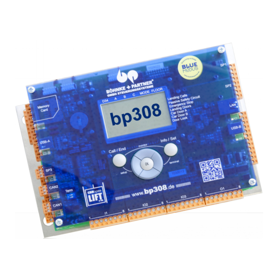
5.7.4 Right Side View 5.7.5 Operator Panel and LCD of the bp308 The operational status of the lift can be determined and parameters set in the control unit and the attached CANopen devices with the help of the graphic LC display and operator panel . -
Page 31: Lift Status Bar
Parameters and times that are not safety-relevant and may be panel to navigate through the changed during system operation such as door times, BlueModus menus. energy saving functions on/off etc. can be set in the bp308 service menu. Installation Manual System »bp308« – Control System »bp308«... -
Page 32: Starting The Service Menu
Confirm by pressing »Ok«. A short notice appears: Service code activated Then you are back in the bp308 start menu . The service code can be changed or reset at any time in the service menu under SUNDRIES > ACCESS CODES > SERVICE CODE . -
Page 33: Call Menu
You can quickly switch between point at which you activated the info menu. You can now switch two sub-menus in the info between the two menus with the click of one button. menu. Installation Manual System »bp308« – Control System »bp308«... -
Page 34: Terminal-Mode
CANopen CiA-417 Lift control application profile. This method has been integrated in the control system bp308 and is available in terminal mode. You can switch to terminal mode by pressing the Info/Set and »Right«... -
Page 35: Program And Parameter Memory
DCP are also mounted on this board. In Fig. 23 addition, the bp308 has 8 inputs and 16 Printed circuit board BPC-04 and the arrangement of its key calls, which can also parameterised as components and interfaces. -
Page 36: Software Update
USB stick in the USB-A connection of the bp308. Switch on the controller and hold down the »Call/End« and »Info/Set« for approximately 2 seconds to start the LPCmon monitor- ing program. -
Page 37: Control System Bp308 And Frequency Inverter Together In One Cabinet
1 m and 1.6 m height. This corres- ponds to a sound level somewhere between a turned-down radio [40 db(A)] and a normal conversation [60 db(A )]. -
Page 38: Easy Service - Thanks To Clear Layout Assembly
15 kW. Systems with a higher power can be supplied on demand . 5.7.15 Control Cabinet with bp308 unit Control cabinet: Structured paint RAL 7032 (grey) - Page 39 Legend of the operation elements on the circuit diagrams Parts list for control unit and port assignment Description of CPU and program summary Description of general operation Documentation for acceptance tests (TÜV) of bp308, including current terminal assignment list Installation Manual System »bp308« – Control System »bp308«...
-
Page 40: Standard Features
EN 81, SIA, ÖNORM, DIN, VDE, VBG 4 5.7.16 Standard Features Assembly The system bp308 is supplied ready for installation, mounted on a stable aluminium plate. The electronic unit consists of the stabilized power supply, the power circuit board and the computer board, safely joint and wired. - Page 41 CANopen-interfaces: Interface (CAN high speed) for communication with all components according to the CANopen application pro file CiA-417 USB-A Schnittstelle: Useable for USB modems, USB sticks, Böpa Bluetooth™ or WiFi stick, Installation Manual System »bp308« – Control System »bp308«...
-
Page 42: Optional Features
Memory card: Memory card slot Optional Interfaces RS232, RS422, RS485 with different protocols for transponder, build- ing automation, touch and LCD monitors, gateways for LONworks, Modbus and internet services . 5.7.17 Optional Features 5.7.17.1 Uninterruptible Power Supply (UPS) BÖHNKE + PARTNER supplies control units for the lift industry. A UPS can be fitted to your ordered controller as an option. - Page 43 Please dispose of the old accumulators in accordance with your local waste regulations. Should you experience any problems with the UPS or require safety- related information, please contact the manufacturer at the address stated in the operating instructions. Installation Manual System »bp308« – Control System »bp308«...
-
Page 44: Installation And Commissioning
6 Installation and Commissioning Prior to installing and commissioning this unit carefully read the safety instructions and warnings and pay attention to every warning label attached to the unit. Make sure that the warning labels are read- able at all times and replace missing or damaged labels . TTENTION For safe operation of the device it is necessary that skilled personnel properly installs and commissions it in adherence to the warnings... -
Page 45: Preparation
CAN, LON, Ethernet and telephone must be laid separately from the load lines! • When installing the control unit, you must adhere to the technical data that has been used during production according your order. Installation Manual System »bp308« – Installation and Commissioning... -
Page 46: Installation Of The Controller System Bp308
The control system bp308 is supplied on an aluminium base plate. It has got four drill holes for fixation. The plate may be fixed through these holes only. -
Page 47: Fixation Kits For Absolute Encoder
The absolute encoder is mounted to the guide rail in the shaft. It is driven by a toothed belt with a non-slip connection to the car via a deflection pulley. Fig. 28 Fixation kits for mounting in the shaft (Type S100). Installation Manual System »bp308« – Installation and Commissioning... -
Page 48: Assembly On The Car
6.6.3 Assembly on the Car A variant of the above-mentioned mounting is the mounting of the absolute encoder on the car. A toothed belt tightened from the shaft head down to the shaft pit drives the absolute encoder. On one hand you have got the advantage of a shorter toothed belt, on the other hand the disadvantage that the toothed belt may generate a rolling sound when the toothed reel runs along at high speed. -
Page 49: Assembly Of The Magnet Switches
Level position switch up Normally open Level position switch down Normally open S553 Zone switch "A" Normally open S554 Zone switch "B" Normally open Fig. 30 Example of a pulse diagram with magnet switches. Installation Manual System »bp308« – Installation and Commissioning... -
Page 50: Electrical Installation
7 Electrical Installation 7.1 Preparation Prior to installing and commissioning this unit carefully read the safety instructions and warnings and pay attention to every warning label attached to the unit. Make sure that the warning labels are read- able at all times and replace missing or damaged labels. ATTENTION! DANGEROUS VOLTAGE •... -
Page 51: Interference Suppression And Hints
! • Should you have any question concerning the EMC Directive please ask our service team . • Please also pay attention to the information concerning cable shielding (section 7.3) Installation Manual System »bp308« – Electrical Installation... - Page 52 Please consider the following measures: • The control system bp308 exclusively serves as an information processing device within the lift control system. All control signals are processed by positive circuitry or via the CAN Bus. The Safety Regulations TRA and DIN EN 81 are not restricted by the elec- tronic information processing.
- Page 53 The RC combina- tions are radially connected to the motor coil (the RC combination of BÖHNKE + PARTNER is universally usable). • Interference suppression means are to be properly installed. Installation Manual System »bp308« – Electrical Installation...
- Page 54 Fig. 31 Interference suppression circuit diagrams...
-
Page 55: Connection Of Shielded Cables
Meanings of the abbreviations (functional groups): A - Modules made by BÖHNKE + PARTNER, inverters C - Separate condensers Installation Manual System »bp308« – Electrical Installation... - Page 56 D - Diodes (e.g.: free- running diodes of DC relay ) E - Illumination (230 V AC – 240 V AC [e.g.: E5 = cabin light]) F - Fuses (e.g.: F2 = control fuse) G - Incremental encoder, tacho generator (analogue, digital) H - Analogue signals, visible and audible (6 V DC - 24 V DC [e.g.
- Page 57 220-240 V AC. The safety circuit functions are independent from those of the con- trol system bp308. In case of a malfunction, the operational voltage of the output module for control elements is cut off.
-
Page 58: Sample Circuit Diagram Of A Rope Traction Lift
7.5 Sample Circuit Diagram of a Rope Traction lift Fig. 35 Wiring of the machine room Fig. 36 Car wiring... -
Page 59: Sample Circuit Diagram Of A Hydraulically Operated Lift
7.6 Sample Circuit Diagram of a Hydraulically Operated lift Fig. 37 Wiring of the machine room Fig. 38 Car wiring Installation Manual System »bp308« – Electrical Installation... -
Page 60: Electrical Installation
EMC wiring directives. 7.8 Bus Connection The lift control systems bp308 comes with the CAN Bus according to application profile CiA-417. This profile describes the physical para- meters of the bus lines as well as the topology. There are generally special rules for the wiring of bus systems. -
Page 61: Colours Of The Cables
Fig. 41 Additional lines are connected by the use of repeater or gateways Fig. 42 Nodes are always to be wired in line. Installation Manual System »bp308« – Electrical Installation... -
Page 62: Example Of A Correct Topology
7.8.4 Example of a Correct Topology 7.8.4.1 Control Unit of an lift Out of a Group From the picture you can see the line structure and the terminations of the control unit of an lift out of a group. The car bus is blue and group bus red. -
Page 63: Group Of Two Lifts In One Line
In this case, the terminations are to be adapted (refer to controls of a single lift ). Fig. 44 Topology of a group of two lifts in one line only. Installation Manual System »bp308« – Electrical Installation... -
Page 64: Group Of Two Lifts In Three Lines
7.8.4.3 Group of Two lifts in Three Lines On the picture you can see the topology of a bus for the landing calls of a group of two lifts in three lines. As the line structure cannot be realised for more than two lines, gateways are used in order that each single line forms a real line itself. -
Page 65: Group Of Two Lifts In Two Lines
In this case, the terminations are to be adapted (refer to controls of a single lift). Fig. 46 Topology of a group of two lifts in two lines. Installation Manual System »bp308« – Electrical Installation... -
Page 66: Pin Assignments
7.8.5 Pin Assignments The CANopen standard stipulates the pin assignments of the most common plug connectors. The application profile for lifts recom- mends the following plug connectors for lift components: • D-Sub 9pins • RJ45 • Open-style-plug connector 7.8.5.1 Pin Assignment of D-Sub Plug Connector with 9 Pins Signal Description Reserved... -
Page 67: Pin-Assignment Of The Open-Style-Connector
CAP-01/02 - landing call units landings 1 to 50 (e.g. line 1 or door B) Default node ID (preset of inventory components such as CAP-01/02 or CIO-01) Flash update bootloader BÖHNKE + PARTNER supply the lift control unit with all node IDs already present. Installation Manual System »bp308« – Electrical Installation... -
Page 68: Travelling Cable To The Car Top Box
7.9 Travelling Cable to the Car Top Box The car terminal box is connected by a travelling cable type 16G0,75+8x(3xAWG22)+3x(2xAWG22) C 4.7x79.1 sw. Please read the assignment of the wires from the enclosed circuit diagrams. Wire Terminal Function X92:4 Socket of terminal box X92:LN Neutral conductor light X94:48... -
Page 69: Selection Of The Frequency Inverter
It is an RS485 point-to-point connection. The DCP interface is put on the top 3-pole plug connector on the left side of the BPC in bp308. The pin assignment is given in the fol- lowing table. 7.10.2.1... -
Page 70: Wiring In Parallel With Rvm-01
one side of the inverter only. Ensure a full-surface connection (refer to section 7.3).The maximum cable-length for the DCP connection is 600 m. 7.10.3 Wiring in Parallel with RVM-01 The controller/pre-control module »RVM-01« selects all known invert- ers that do not feature the option of a serial interface. The control sig- nals for the different speeds and directions of travel are put out via 7 potential free relays equipped with gold-plated double contacts to ascertain reliable switching for every possible demand on the... - Page 71 »RV1« is activated and right if »RV2« is activated (as seen from the motor side of the shaft. Additional speed V_ZE1 Additional speed V_ZE2 Installation Manual System »bp308« – Electrical Installation...
-
Page 72: Installation Of The Absolute Encoder
Preferably, these additional speeds are to be used for inspection and emergency operations. Additional speed V_ZE3 This input may activate different functions of the inverter, to be preset in the menu INTERFACES. The additional speed V_ZE3 was selected a factory. Brake chopper temperature. -
Page 73: Data Lines To The Remote Diagnostics
If remote diagnostics are to be carried out via an analogue telephone connection, the data is transmitted via an analogue modem, which can be connected to the USB-A slot of the BP308. This has to be a "real" hardware modem and not a software modem. The USB modems for the bp306 supplied by BÖHNKE + PARTNER are "real"... -
Page 74: Lon
Connection to a LONworks network – e.g. within the building automa- tion system – is carried out via the ASBuP interface. It is connected to the optional SP1 connector of bp308 as well as a RJ45 plug to the LON network. -
Page 75: Commissioning Instructions
• The control unit has been mounted and installed according to this manual. • Operating and setting possibilities are all known (see user manual bp308 ). • The valid EMC rules (electro-magnetic compatibility) are complied with! • The power circuit, control circuit and safety circuit have been con- nected and checked according to this manual (see check-list). -
Page 76: Preparation
• You must therefore ascertain before connecting the STM-02 device that there really is no connection between the PE terminal of the lift control unit and terminal 100 of bp308. Use an Ohm-meter or a cir- cuit continuity tester. • After having completed these checks, you can connect the voltage testing module STM-02 as shown in the diagram enclosed. -
Page 77: Technical Tips Concerning The Control Unit
V DC is not earthed. With the lift system switched on, any over- voltage within the control circuit towards »PE« does not result in a fault current, removing the risk of bp308 components being destroyed AUTION • STM-02 signalises over-voltages in the control circuit with an LED and a buzzer. - Page 78 The safety rules DIN EN 81 are not infringed by electronic data processing. 8. The control system bp308 was examined by the relevant authorit- ies and has been awarded an EC type examination certificate. In section “Product Certifications”...
- Page 79 24 V DC) is to be connected to the protective earth conductor (PE) of the mains supply . - Terminal 100 (minus 24 V DC) of bp308 is to be connected to the PE terminal in the control unit, thus avoiding a floating net- work and making it possible to recognize an earth leakage of the signal voltage (+24 V DC) at once .
- Page 80 26. In the inspection control mode, terminals 101 and 102 of bp308 and/or CLK-01 lose their current (see DIN EN 81, 14.2.1.3): - All cabin and landing calls are deleted and blocked , - Doors cannot be opened, automatic door movement is disabled,...
- Page 81 b) Temperature too high value>2.7 kOhm = PTC thermistor has responded, refer to fault messages Settings in the setup menu: Rope traction lift Immediate stop without switch-off Stop at next flush-level switch ahead without switch-off Immediate stop with switch-off Stop at next flush-level switch ahead with switch-off Hydraulically operated lift Stop with return without switch-off Stop without return without switch-off...
- Page 82 Example: A defective hydraulic hose or a defective threaded hose coupling causes the hydraulic oil to be pumped into the shaft pit! 44. The hydraulically operated lift must conform to all stipulations set out in the relevant local "water protection regulations"! Installation Manual System »bp308« – Commissioning Instructions...
- Page 83 45. Runtime monitoring is a standard function in every lift control unit. To check this function, proceed as follows (DIN EN 81, part 1, 12.10 and part 2, 12.12): Floor selector using magnet switches a) Stop the car at the bottom landing, b) Disconnect pulse transmitter from S75 and S77, c) Enter travel command to top landing , d) Car passes by the pulse transmitters without receiving the...
-
Page 84: Checks Before Starting The Control Unit
Safety circuit contacts of well and car have been mounted and Yes □ installed. Have you paid attention to the safety instructions in section 2 Yes □ "Safety Information" and followed them ? Installation Manual System »bp308« – Commissioning Instructions... - Page 85 • circuit diagrams, unambiguously identified by the serial number of the control unit (e.g.: : 93401) • Parts lists, EC type examination certificate and declaration of conformity for System bp308, • Terminal plans, • Basic settings, • Port assignment plans and general tips concerning the control system bp308.
-
Page 86: Switching The Mains Voltage
Is the voltage test module STM-02 not sending out any acoustic or Yes □ optical warning signals ? Does the LCD show no problem with the voltage in the bp308 sys- Yes □ tem ? Does the voltage in the power supply unit of bp308 between ter- Yes □... -
Page 87: Checking The Bus Lines
BÖHNKE + PARTNER. Check whether they correspond to the particularities on site. If neces- sary, adapt the parameters on the display of the bp308 (refer to user manual bp308. 8.6.1 Checking the Bus Lines... -
Page 88: Checking The Bus Termination
CAN adapter used for configur- Has bp308 been set to the correct drive/inverter type, ing CAN components. Has the DCP interface been activated in bp308 and in the inverter, Have both units (control and drive) been set to the same protocol (DCP3/DCP4+), Are there no malfunctions at present. -
Page 89: First Travel With Emergency Controls
Travel commands are controlled and monitored by the control sys- tem bp308. If a photocell is integrated, terminal X7.53 (door B: X7.56) must be live. -
Page 90: First Travel With Inspection Controls
Travel commands are controlled and monitored by the control sys- tem bp308. All safety circuit devices remain operational. If any of the contacts in the safety circuit are interrupted, the lift is shut down immediately. - Page 91 automatic lift operation. Moving the car and the door is only possible by activating the command buttons of the inspection control unit (dead man's circuit) in absence of the emergency control functions (either switched off or not installed). In addition, activation of a stop button, which can only be returned to its original position by turning it, can cause an emergency stop.
-
Page 92: Course Of A Regulated Two Speed Travel (Summary)
(6 to 7). As soon as the motor stands still, the inverter closes the electro-magnetic brake MB (7 to 8). The main con- tactors are switched off with a time delay through the RF signal. Installation Manual System »bp308« – Commissioning Instructions... -
Page 93: Disconnection Points For The High Travelling Speed (V3)
• The electromagnetic blocking brake must be switched on and off without time delay through relay MB, in order to ensure that the inverter initiates smooth starts and stops. • The main contactors to the motor must be switched on and off without time delay through relay RB to ensure smooth starts and stops . -
Page 94: Course Of A Direct Travel With Dcp (Summary)
Fig. 60 Speed curve of a travel with direct landing approach Installation Manual System »bp308« – Commissioning Instructions... -
Page 95: Commissioning Of The Floor Selector System
8.11 Commissioning of the Floor selector System As soon as it possible to travel with inspection control, the transmit- ters of the Floor selector system can be mounted and installed. It can be either magnet switches, absolute rotary shaft encoders (AWG-05) or linear encoder systems such as USP or laser positioning systems. -
Page 96: Basic Settings
Floor selector system as described in section 6.6. 8.11.2 Basic Settings Fig. 62 After installing the CAN transmitter system (see installation manual Activating the assembly travel enclosed), select the following presets in the bp308 setup menu: to move the car without encoder Setup menu: > P ARAMETER system. -
Page 97: Read-In Travel With Absolute Encoder
8.11.3 Read-in Travel with Absolute Encoder After completing all these settings, you can initiate the read-in travel in compliance with the following instructions. During the read-in travel, the flush-level positions of every landing are precisely determ- ined and memorised in the program memory. From the data gathered by the read-in travel combined with the parameters set, the control program calculates the virtual floor selector. -
Page 98: Travel Speeds
INFO V0 < V1 < V2 < V3 < V4 < V5 < V6 < V7! Fig. 65 Example of a speed curve when a DCP-03 connection with V4 nominal speed is selected. Installation Manual System »bp308« – Commissioning Instructions... - Page 99 INFO For speed controlled lifts, you have to adhere to the instructions of the frequency inverter manufacturer! Deceleration distance V1..7 = Deceleration sets in toward the landing Deceleration distance VI = Deceleration sets in during Deceleration sets in during VR = Deceleration sets in with emer- gency control (if supported separately by the drive unit) Deceleration distance V...
- Page 100 (V0) before reaching the bottom landing. Settings in the setup menu: > F UNCTIONS > F LOOR SELECTOR > (S81/82) DECELERATION Fig. 66 Pulse diagram with magnet switches and AWG-05 Installation Manual System »bp308« – Commissioning Instructions...
-
Page 101: Impulse Diagrams Of Absolute Encoder, Without Short Distance Landing
8.11.6 Impulse diagrams of Absolute Encoder, without Short Distance Landing Fig. 67 Pulse diagram related to deceleration distances in the flush-level area Fig. 68 Pulse diagram related to the zones in the flush-level area... -
Page 102: Impulse Diagrams Of Absolute Encoder With Short Distance Landing
8.11.7 Impulse diagrams of Absolute Encoder with Short Distance Landing Fig. 69 Pulse diagram 3, deceleration distances and flush-level area Installation Manual System »bp308« – Commissioning Instructions... -
Page 103: First Travel With Normal Operation Controls
Have you followed every item of the previous check-lists (see sec- Yes □ tion 8.4 and following)? Does the bp308 LC display fail to display current malfunctions ? Yes □ Emergency control and inspection control are functioning as Yes □... -
Page 104: Optimising The Travelling Behaviour
As described in section 8.16 data remote diagnostics can be carried out via different kinds of networks. If wiring has been completed according to the circuit diagrams supplied, you can establish the con- nection. Installation Manual System »bp308« – Commissioning Instructions... -
Page 105: Commissioning Of A Modem
INFO To correctly commission our software WinMOS ® 300, please follow the specifications and instructions of the WinMOS ® 300 manual. Be aware that you may unwittingly shut-down the lift by entering incorrect parameters (e.g. setting runtime monitor value too low ). If you want to connect a modem parallel with an emergency call system to a mutual telephone connection, first ask approval from BÖHNKE + PARTNER. -
Page 106: Completing The Commissioning
If third parties (e.g. janitor) have access to the system, please pro- tect access to the menus by assigning a setup and a service code. Installation Manual System »bp308« – Commissioning Instructions... -
Page 107: Troubleshooting
OK button or by quickly switching off the opera- tional voltage. 9.1 Monitoring Routines The bp308 software monitors a lot of signals for correct behaviour and time characteristics. If any discrepancy arises, a corresponding error message is stored in the event log and time stamped. You can read how often this error occurred from the malfunction list. - Page 108 (lift will get blocked if fault message is thrown). TIP ABOUT MONITORING FUNCTIONS Monitoring functions are directly displayed in the DIAGNOSTICS → MALFUNCTIONS menu. They are registered and stored in the event log and the malfunction list. Installation Manual System »bp308« – Troubleshooting...
-
Page 109: Malfunction Information
9.3 Reporting of Malfunctions Every bp308 has been prepared for remote diagnostics. The control system bp308 is fitted with a LAN connection for attaching the control unit to an Intranet or the Internet. If the unit is to be connected via the telephone, an analogue modem can be connected to the USB-A interface. -
Page 110: Malfunction Stack
Press »OK« to delete the stack and also answer the security ques- tion by pressing »OK«. In order to create a stringent protocol, we recommend deleting the event log only after having transmitted the entries to the WinMOS 300 centre. ® Installation Manual System »bp308« – Troubleshooting... -
Page 111: Messages
9.6 Messages Messages inform you about special conditions within the system and that the lift might have restricted functionality. All data resulting in the message at that point is reported. Examples: Landing controls switched off Emergency stop activated in the car Inspection controls switched on Emergency controls switched on Cabin priority functions switched on... -
Page 112: Repair Work
To save time and money, please call us and state the serial number of the control unit and the circuit diagrams. Installation Manual System »bp308« – Troubleshooting... -
Page 113: Maintenance
10 Maintenance Prior to carrying out maintenance work, we recommend reporting it in the bp308 service menu under MAINTENANCE > MAINTEN- ANCE FUNCTIONS > MAINTENANCE ON. From that point, the system no longer sends error messages via remote data transfer and the system is displayed as "undergoing maintenance“. -
Page 114: Appendix
Appendix A Menu Navigation bp308 Version 88D2312 (29/08/2013) -
Page 116: B Service Menu Quick Reference
B Service Menu Quick Reference Program Version: 88D2402B (14/02/2014) Service Menu ============ +- Diagnostics +- Malfunctions +- Messages +- Storage +- Malfunction stack +- Message stack +- Maintenance stack +- Malfunction list +- Signals +- Shaft-Signals +- Port I/O +- Calls +- Controller +- Ins/Ero inputs +- Evacuation inputs... - Page 117 +- Door B inputs +- Door B outputs +- Door C inputs +- Door C outputs +- Load measuring +- UPS +- Energy meter +- Card reader +- Group +- Timer +- Door A Timer +- Door B Timer +- Door C Timer +- State +- Interfaces +- CAN 1 port...
- Page 118 - Nederlands - Français - Italiana - Svenska - Polski - Russian - Türkçe - Magyar * Startup Dialog - Current malfunction or message [Default] - Trip counter and hour meter * Auto adjust. daylight-saving time - off - on [Default] +- Controller +- General * Door gong...
- Page 119 - off [Default] * Hall lantern - turn on at slowing point [Default] - turn on when doors are unlocked - turn on when doors open - turn on when doors are fully open * Hall lantern blinking on priority - off - on [Default] * Hall lantern blinking on guest call...
- Page 120 * Prevent disabling extra landing calls - off [Default] - on * Process next extra landing call, if car not occupied - off [Default] - on * Landing call at remote off floor opens door - off [Default] - on * Landing calls on loadtime operation - collective [Default] - cancel...
- Page 121 * Car calls on high priority operation - one alterable car call [Default] - collect car calls * Trip to high priority floor with no load only - off [Default] - on * Collect high priority calls - off [Default] - on * Prevent disabling of high priority landing calls - off [Default]...
- Page 122 0..65000 [0] mm * V2 0..65000 [0] mm * V3 0..65000 [0] mm * V4 0..65000 [0] mm * V5 0..65000 [0] mm * V6 0..65000 [0] mm * V7 0..65000 [0] mm * VN (Releveling velocity) 0..65000 [5] mm * VI (Inspection velocity) 0..65000 [750] mm * VR (Emerg.
- Page 123 0..65000 [0] mm * VR (Emerg. rescue velocity) 0..65000 [0] mm +- Drive profile * Acceleration 100..2000 [800] mm/s² * Deceleration 100..2000 [800] mm/s² * Starting jerk 100..2000 [500] mm/s³ * Travel jerk 100..2000 [1000] mm/s³ * Slowing jerk 100..2000 [1000] mm/s³ * Stopping jerk 100..2000 [500] mm/s³...
- Page 124 - SC X5.16 (Shaft door) [Default] - SC X5.17 (Car door A) - SC X5.18 (Car door B) * Hall call must be pending for signal door close (66) - on [Default] - off * Advance warning close door until door is closed - off [Default] - on * Keep doors open when idle 1..127...
- Page 125 * Extra dwell for handicapped accessible hall calls 1..30 [5] s * Parking off/10..65535 [off] s * If park floor changed, re-park after off/10..65535 [15] s * Allocation time low priority call 10..9999 [60] s * Allocation time high priority call 10..9999 [60] s * Allocation time direct run or lift allocation 10..9999 [60] s...
- Page 126 off/1..60 [20] s * Door locking monitoring off/1..60 [10] s * Manual door monitoring time in group operation off/1..255 [off] s * Start control 1..45 [15] s * Driving monitoring 1..45 [45] s * Deceleration control 1..30 [15] s * Re-levelling control 1..45 [20] s * Pawl device monitoring lifting/lowering off/1..60 [10] s...
- Page 127 +- Door times * Dwell time after light curtain 1..20 [1] s * Dwell time after force limit 1..20 [3] s * Dwell time after door open button 1..20 [4] s * Close doors when idle off/1..240 [8] s * Advance warning close idle door off/1..60 [off] s * Advance warning open door off/1..15 [off] s...
- Page 128 off/1..16 [off] * Parking in hidden position off/1..1200 [off] mm * Enable parking at floors with no doors - off [Default] - on * Control floor remote off off/1..16 [off] * Remote off floor off/1..16 [off] * Remote off in hidden position off/1..1200 [off] mm * Peak-up floor off/1..16 [off]...
- Page 129 10..350 [150] mm * Lower door zone 10..350 [150] mm * Upper level zone 1..350 [10] mm * Lower level zone 1..350 [10] mm * Re-level area up 2..350 [20] mm * Re-level area down 2..350 [20] mm * Pawl device lifting distance 0..500 [50] mm * Inspection stop before top floor level off/1..3000 [off] mm...
- Page 130 * Doors during maintenance - Normal [Default] - Keep doors closed, until reset - Keep doors closed, still after reset * Drive to the service floor off/1..16 [off] * Enable the service position to be in the shaft pit area - off [Default] - on * Enable assembly mode...
- Page 131 +- Save parameters +- Save factory default +- Testing +- UCM-Test (A3) * Code for Tests * UCM-test (A3) with doors open - off - on [Default] * Enable UCM-test (A3) - off [Default] - on, using drive - on, using brake +- Brake test * Code for Tests * Brake test velocity...
- Page 132 +- Landings up extra +- Landings down extra +- Priority calls +- High priority calls +- Tripcnt/hours meter +- System info +- Sundries +- Setup info +- Access codes * Service code * Info code +- Date/Time +- Commands * Revoke remote off via remote monitoring - off [Default] - Execute * Revoke landing control off via remote monitoring...
-
Page 133: C Setup Menu Quick Reference
C Setup Menu Quick Reference Program Version: 88D2402B (14/02/2014) Setup Menu ========== +- Parameter +- Lift data * Top terminal floor 2..127 [16] * Bottom terminal floor 1..126 [1] * Type of lift - Traction lift [Default] - Hydraulic lift * Drive type traction - Single speed - Two speed [Default]... - Page 134 * Floor selector type - Floor selector emulation - Absolute encoder (CAN) [Default] - Using 4 switches impulse & level - Using 6 switches 2 impulse & 2 level - Absolute encoder emulation - Absolute encoder AWG-05 (RS-485) * Protective Circuit (SMZ) - Off [Default] - on, without blocking - on, with blocking...
- Page 135 - Execute +- Doors +- Door settings * Door count 1..3 [1] * Operating mode - Selective [Default] - Selective, alternate locked - simultaneous (not selective) +- Door table * Door table 1..127 * Second door table (signal 80) 1..127 * Third door table (signal 380) 1..127 +- Door A settings * Landing door type...
- Page 136 * Safety light curtains - off [Default] - on * Retiring cam - off [Default] - on * Door B enabling (436) - off [Default] - on * Door close sig. on, if Ins/Ero - off [Default] - on +- Door C settings * Landing door type - Automatically operated [Default] - Manually operated...
- Page 137 - GDB - SAP - SLP - AWG-05 (RS-485) - USV (Effekta) - LIN bus master * Modem device - Analog modem - ISDN - GSM - FirePlug (Bluetooth) - EA-GSM Modem (Leitronic) - EA-GSM Internet (Leitronic) - GPRS/UMTS +- Serial ports +- Serial interface 1 * Function - RDT-300...
- Page 138 - DCP logging - APS logging - Energy meter (UMG) - GDB - SAP - SLP - AWG-05 (RS-485) - USV (Effekta) - LIN bus master * Baud rate - 1200 Bit/s - 2400 Bit/s - 4800 Bit/s - 9600 Bit/s - 19200 Bit/s - 38400 Bit/s - 57600 Bit/s...
- Page 139 - Energy meter (UMG) - GDB - SAP - SLP - AWG-05 (RS-485) - USV (Effekta) - LIN bus master * Baud rate - 1200 Bit/s - 2400 Bit/s - 4800 Bit/s - 9600 Bit/s - 19200 Bit/s - 38400 Bit/s [Default] - 57600 Bit/s - 115200 Bit/s +- USB-B (device)
- Page 140 * IP Callback server * Host name Callback server * Port Callback server (Call Acceptance) 1..65535 [9001] * Access password callback server +- Network connection * Interface - off [Default] - on * IP address * Subnet-mask * Gateway * Primary DNS * Secondary DNS * Function - RDT-300 [Default]...
- Page 141 - Low priority hall call acknowledge - Door gong - Door gong up - Door gong down * Drive direction mapped to floor byte - off [Default] - on +- Functions +- User Interface * Language - English - Deutsch [Default] - Nederlands - Français - Italiana...
- Page 142 * General monitoring 2 (53) delay off/0.1..6500.0 [off] s * Generic monitoring 3 (257) - off [Default] - on, stop at floor - on, immediately - on, blocked mode at floor - on, blocked mode immediately * Text generic monitoring 3 (257) - Generic monitoring [Default] - UPS monitoring - Vandalism monitoring...
- Page 143 - off [Default] - on * Max. Evacuation velocity - V0 (Creeping velocity) - V1 * Evacuation direction - none [Default] - up - down - Set direction by using full load limit * Doors at fire emergency power floor - Standard - Remains closed - Remains open [Default]...
- Page 144 * Unlock disabled floors - off - on [Default] * Ignore overload on fire service - off [Default] - on * Cancel remote off - off - on [Default] * Doors - Peep door function [Default] - Normal operation * Homing the car by turning off/on the fire recall (125) key within 5 s - on [Default] - off * Car calls need constant pressure...
- Page 145 * Distance to floor factor 1..4 [1] * Penalty for directional change off/1..4 [2] * Send group settings to all active group members - off [Default] - Execute +- Guest Calls * Function - off [Default] - on, send lift by car call only - on, send lift by hold time expired - on, send lift by car call or hold time expired - on, send lift by enable signal only...
- Page 146 - V3 - V4 - V5 - V6 - V7 - VN (Releveling velocity) - VI (Inspection velocity) - VR (Emerg. rescue velocity) * Velocity docking service floor 1..8 - V0 (Creeping velocity) [Default] - V1 - V2 - V3 - V4 - V5 - V6...
- Page 147 +- General * Drive with integrated contactors - off [Default] - on * Enable of drive control (693) - off [Default] - Up - Down - No direction * Enable of drive control (693) - off [Default] - Up - Down - No direction * Fast start while doors are closing - off [Default]...
- Page 148 - on, stop immediately blocked * Low pressure monitoring (51) - off [Default] - on, stop immediately - on, stop immediately blocked * Safety valve monitoring 2 UCM/A3 - off [Default] - on * Inspection speed - Slow [Default] - Fast * Transmit mode - event-driven [Default] - Cyclic...
- Page 149 * Info code * RD code (Monitoring code) * Code for Tests +- Various numbers * Lift number * Controller number * RD-number (Monitoring id) * Phone number 1 * Phone number 2 * Phone number 3 * Phone number 4 * Phone number 5 * Phone number 6 * Phone number 7...
- Page 151 Index Control system bp308.....21, 27, 47, 53, 61 Subject Index Control Unit of an lift Out of a Group....63 Absolute Encoder........47, 104 Cooling air............45 Aggressive mediums........45 Correction switch..........50 Application profile CiA-417......25, 61 Creeping correction system......85 Application profile for lifts........67 Current-operated circuit breaker.....81 Assembling and operating requirements..11...
- Page 152 Index Functional Description of Voltage Test Module Mounting racks..........53 ................79 Notification............9 Gateway..........65, 107 Open-style-plug connector......67 Group of Two lifts ...........65 Operating temperature........45 Guide rail............48 Operator Panel..........31 Hydraulically Operated lift.......60 Optimising the Travelling Behaviour....106 Impulse ............50 Over-current release........81 Impulse diagram..........50 Parameter memory.........36 Impulse diagram with magnet switches and .
- Page 153 Topology............73 Topology of a bus..........65 Topology of the Network ........62 Travel speed..........100 Travel Speed..........100 Travelling Cable..........69 Troubleshooting..........109 UPS..............80 USB stick............37 USB-A connection...........37 Variants of bp308..........29 Vent slots............45 Voltage fluctuations.........54 Voltage-Test Module ........78 Wall-mounted..........47 Warning labels..........9 WinMOS®300.........21, 108, 111 Zone switch.............50...
Need help?
Do you have a question about the bp308 and is the answer not in the manual?
Questions and answers