Table of Contents
Advertisement
Quick Links
intelligent motion systems, inc.
Excellence in Motion
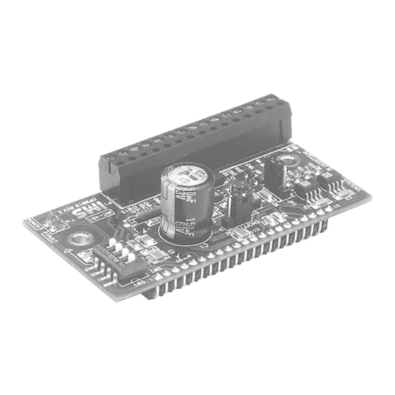
INT-481
INTERFACE BOARD FOR THE IM481H DRIVER
QUICK REFERENCE
370 N. MAIN ST., PO BOX 457, MARLBOROUGH, CT 06447
PH: (860) 295-6102, FAX: (860) 295-6107
Internet: www.imshome.com, E-Mail: info@imshome.com
I N T - 4 8 1 Q u i c k R e f e r e n c e G u i d e
The primary function of this Quick Reference Guide is to aquaint
the user with the specifications, basic wiring and configuration of
the INT-481 Interface Board for the IM481H Driver. More
information is available on both products in the full IM481H
product manual saved in Acrobat PDF format on the IMS Product
CD, shipped with the product. It also may be downloaded from
the IMS web site at http://www.imshome.com.
N o t e s A n d W a r n i n g s
Please observe the following when handling, connecting and using
your INT-481 Interface Board. Failure to observe these points may
result in damage to the Interface Board or the IM481H Driver. All
warranty and disclaimer information is located in the full product
manual on the CD and should be referenced for more information.
WARNING! The INT-481 Interface Board and IM481H Driver
components are sensitive to Electrostatic Discharge (ESD). All
handling should be done at an ESD protected workstation.
WARNING! Hazardous Voltage Levels may be present if you are
using an open frame power supply to power the INT-481 Interface
Board and IM481H Driver.
WARNING! Ensure that the Power Supply output voltage does not
exceed the maximum input voltage of the IM481H Driver.
WARNING! Do not operate the IM481H Driver without a
Current Adjustment Resistor! If you are installing the INT-481
Interface Board the resistors may be added to it.
A resistor MUST be placed between the Current Adjust Input (Pin
14) and ground (Pin 13) to keep the IM481H Driver, the INT-481
Interface Board and/or motor in a safe operating range.
WARNING! Do not connect or disconnect the motor leads or the
AC power supply with power applied.
Please see the motor and driver documentation for other warnings
and notes.
E l e c t r i c a l S p e c i f i c a t i o n s *
Opto Supply
Isolated Inputs .......................................... +5 ........................ +40 ........ V
Input Forward Current
Isolated Inputs ............................................ 5 ............................ 1 5 ....... m A
Opto Input Forward Voltage
Isolated Inputs .......................................................... 1 . 5 ...... 1 . 7 ......... V
Reverse Breakdown Voltage
Isolated Inputs ............................................ 5 ............................................... V
Signal Output Current
Full Step, Fault ............................................................................ 2 0 ....... m A
Drain Source Voltage
Full Step, Fault .......................................................................... 1 0 0 ........ V
Drain Source Resistance
= 25mA) .......................... 6 . 5 .......................... Ω
Full Step, Fault, I
DS
* All test data was taken at 25°C and +V = 45 VDC.
For More Information:
See the complete IM481H Product Manual
on the IMS Product CD or at www.imshome.com
Revision 061605
TM
TM
M I N
T Y P
M A X U N I T
I N T - 4 8 1 P 1 C o n n e c t o r P i n A s s i g n m e n t
Pin Name
Pin #
—
—
1
Phase B
Phase B Output
2
Phase B
Phase B Output
—
—
3
Phase A
Phase A Output
4
Phase A
Phase A Output
Enable
When this input is HIGH, motor phases are energized.
5
6
Reset
When LOW, this input will Reset the Driver.
7
Opto Supply
+5 to +24 VDC external Optocoupler power supply.
This input changes the direction of the motor. The physical
Direction
8
direction depends on the connection of the motor windings.
A positive going edge on this input advances the motor one
increment. The size of the increment is dependent on the
Step Clock
9
Microstep Select Inputs.
This Output indicates a short circuit has occurred or a low
Fault
10
was detected on the Fault Input. This Output is active HIGH.
This Output indicates when the driver positions the motor
one Full Step. This output can be used to count the number
11
Full Step
of Full Steps the motor has moved regardless of the
number of Microsteps. This output is active HIGH.
12
+V
+12 to +48 VDC Motor Power Supply.
13
Ground
Power Supply Ground.
Current
Phase Current Adjustment Input. A voltage applied to this
14
Adjust
Input sets the peak Phase Current of the motor.
Phase Current Reduction Input. A resistor connected
between this pin and Pin 14 (if used to set motor current)
Current
15
will proportionately reduce the current in both windings
Reduction
approximately 0.5 seconds after the last positive edge of
the Step Clock Input.
O u t p u t C u r r e n t A d j u s t / C u r r e n t R e d u c t i o n *
The INT-481 utilizes the IM481H's internal current source to
adjust the Output Current of the IM481H. To calculate both the
Run Current and the Reduced Current** (hold) refer to the
IM481H instruction manual. The figure below shows the resistor
connections for both run and hold currents.
21
ENOFF/ENON
1
JP2
Current Adjust Resistor
1/8 W 1% W
Pin 13
*
When connecting both the current reference and current reduction resistors,
connections should be made as short as possible to minimize the noise coupled
into the driver.
** WARNING! DO NOT install the Current Reduction resistor when the JP2 jumper is
in the "ENON" position. See JP2 under "Isolated Inputs".
I s o l a t e d I n p u t s
+5VDC Optocoupler Supply
Pin 7
Step Clock Pin 9
CW/CCW Direction Pin 8
Enable/Disable Pin 5
Reset Pin 6
Typical Opto Isolated Inputs
JP1: If the shunt is placed on the "OPTO" side of the jumper the
power for the Opto Isolators must be provided by the user at Pin
7 on the P1 connector. If the shunt is placed on the "+5V" side of
the jumper then the Opto Isolators will be powered by the
on-board supply and electrical isolation between the inputs and
the drive power will be eliminated.
JP2: If the shunt is placed on the "ENON" side of the jumper then
the drive outputs will be automatically disabled approximately 0.5
seconds after the last step clock input.
NOTE: In this mode the current reduction resister MUST NOT be
used or it will cause erratic operation of the driver. If the shunt is
placed on the "ENOFF" side of the jumper then a current reduc-
tion resister can be used to set the level of current in the motor
after the last step clock input.
21
JP1 And JP2 Jumpers
Description
1
SW1
MS0
MS1
3
MS2
MS3
GRN
RED
LED1
Reduction Adjust Resistor
1/8 W 1% W
Pin 15
Pin 14
+5V
OPTO/+5V
JP1
1
SW1
ENOFF/ENON
MS0
MS1
1
3
MS2
JP2
MS3
ENOFF/ENON
GRN
1
3
RED
LED1
JP2
Advertisement
Table of Contents

Related Manuals for Intelligent Motion Systems INT-481


Summary of Contents for Intelligent Motion Systems INT-481
-
Page 1: Quick Reference
Interface Board the resistors may be added to it. A resistor MUST be placed between the Current Adjust Input (Pin OPTO/+5V 14) and ground (Pin 13) to keep the IM481H Driver, the INT-481 +5VDC Optocoupler Supply Pin 7 Interface Board and/or motor in a safe operating range. - Page 2 ** The hardware items A, B, C, E, F, H, are supplied with the H-481 Heat Sink Kit LED1 but not with the INT-481 Interface Board. NOTE: The torque specification for the #6-32 INT-481 and IM481H mounting screws is 5.0 - 7.0 lbs-in. MSEL Switch Shows 50 Microsteps/Step Selected...
Need help?
Do you have a question about the INT-481 and is the answer not in the manual?
Questions and answers