Table of Contents
Advertisement
Advertisement
Table of Contents

Related Manuals for Datafox Evo 4.3


Summary of Contents for Datafox Evo 4.3
- Page 1 Manual Datafox Evo 4.3 Flexible data collection with method...
- Page 2 Datafox GmbH. The assertion of all rights in this respect is reserved to Datafox GmbH, especially in case of the grant of a patent. The handover of this documentation does not establish a claim to the license or the use of the soft- and hardware.
- Page 3 Datafox MasterIV, SW version xxx.pdf list as shown. The file is located on the Datafox DVD and for download on the homepage. Please also note the instructions in each chapter in the manual. The updates are available on our website under www.datafox.de download.
-
Page 4: Table Of Contents
Color Setting for the Display ..................28 5.2.4.2. Default Setting ......................28 5.2.4.3. Display function buttons on the EVO 4.3 / 2.8 display ..........29 5.2.4.4. Upload images for function buttons of EVO 4.3 / 2.8 ..........29 5.2.4.5. Design examples in the designer ................30 Manual Datafox Evo 4.3... - Page 5 5.3. switch collours of the backligth ................35 5.3.1. Switch lighting depending on the result ..............36 5.4. Installation of the EVO 4.3 Terminal ............... 37 5.5. Connecting of EVO 4.3 .................... 38 5.5.1. Connecting plugs EVO 4.3 ..................38 5.5.2.
- Page 6 5.11.4. Procedure ........................ 135 5.11.5. Process Variants...................... 136 5.11.6. Technical Data of the Fingerprint Module ..............137 tecnical data Evo 4.3 Terminal 6.1. communication modules ..................139 6.2. access modules ..................... 139 6.3. Module digital in and out ..................139 6.4.
-
Page 7: For You Safty
For you Safty Safety Information for Datafox Products The EVO 4.3 must only be operated according to the instructions given in the manual. Do no insert any foreign objects into the openings and ports. The device must not be opened. All maintenance work must only be performed by authorized specialists. -
Page 8: Introduction
GPRS, USB etc. It fulfills all conditions for a flexible usage not only for personnel or order time re- cording but also for further scopes. This constitutes a real added value. The powerful tools Datafox- StudioIV and DLL facilitate quick and easy integration in any IT solutions. Due to scalability, numer- ous options are available. -
Page 9: Typography Of The Documentation
Due to technical development, illustrations, function steps, procedures and technical data may vary slightly. The Datafox device has been developed for the purpose of creating a flexible and easily inte- grated terminal for data recording serving for a great variety of applications. The device is robust and easy to use. - Page 10 With some practice it will be possible to create a complete compilation for the EVO 4.3 within half an hour. If you need functions that are not available, please contact us. Note: If you need support for the compilation of setups, we offer you our services. Due to...
-
Page 11: Intended Use And Environmental Protection
In order to ensure maximum battery life, it is recommended to recharge the battery only after com- plete discharge. See respective type label of the device EVO 4.3. 3.3. Environmental Influences Extreme environmental influences may damage or destroy the device and should be avoided. This includes fire, extreme sunlight, water, extreme cold and extreme heat. -
Page 12: Mounting Outdoors
Mounting outdoors 3.4.1. Degree of protection The terminal EVO 4.3 has IP65 on the front side. On the backside, only the cable feed / connection area is a restriction with respect to the IP class. If the device is mounted on a flat base, the connection area is protected so that the entire system has... -
Page 13: Repair
Except for the battery replacement in mobile devices , Datafox devices are maintenance-free and must only be opened by authorized professionals. In case of defects, please contact your dealer or the Datafox service hotline. If a definite defect is present, you can also send the device directly to Datafox. 3.6. Cleaning CAUTION Risk of explosion if batteries are replaced improperly. -
Page 14: Disposal
The correct disposal of electrical and electronic equipment protects human life and the environment. For more information regarding the disposal of electrical and electronic equipment, please contact your local authorities or waste disposal companies. Manual Datafox Evo 4.3 Page 8 Date: 27.12.2017 V 04.03.09.XX... -
Page 15: System Requirements / Hardware
4.2. Requirements for Operating Datafox Devices In order to operate the Datafox device, you need a 230 V power connection for the Datafox power supply. Depending on the main communication set, you need a corresponding transfer medium or connection cable. -
Page 16: Kompatibilität Compatibility
Device files (*.hex) of the MasterIV devices are delivered in a common firmware file archive. It has the file extension DFZ (stands for Datafox Zip). Now simply the firmware file archives (*.dfz) are in- dicated instead of the device files (*.hex). This applies to the DatafoxStudioIV and the DLL. The in- dication of device files (*.hex) is still possible. -
Page 17: Device Firmware And Communications Dll
A newer version of DatafoxStudioIV does not work with an older DLL. 4.3.6. DatafoxStudioIV and Device Setup With the DatafoxStudioIV, you create a device setup (application program) for the Datafox device. That means that in the setup only those functions were defined which were available in the Data- foxStudioIV version at the time of the setup creation. -
Page 18: Update / Downgrade
When performing a firmware downgrade the firmware has to be transmitted to the device twice. This has technical reasons. Errors shown on the display of the device after the first transfer can be ignored. Manual Datafox Evo 4.3 Page 12 Date: 27.12.2017 V 04.03.09.XX... -
Page 19: Device
After establishing the power supply the device will switch on automatically. The EVO 4.3 automatically starts booting, recognition of the hardware options and loading the setup. After having finished booting, the device switches to operation. Now the EVO 4.3 is ready for use. ... -
Page 20: Guidline For Commissioning
► Finishing installation of the device ► Setting for man communication 5.1.1.3. Troubleshooting during Commissioning ► Please see the FAQ on our website: http://www.datafox.de/faq-de.html. ► Tips: o Connection to the device cannot be set up via TCP/IP Check IP in the device and the application (studio) ... -
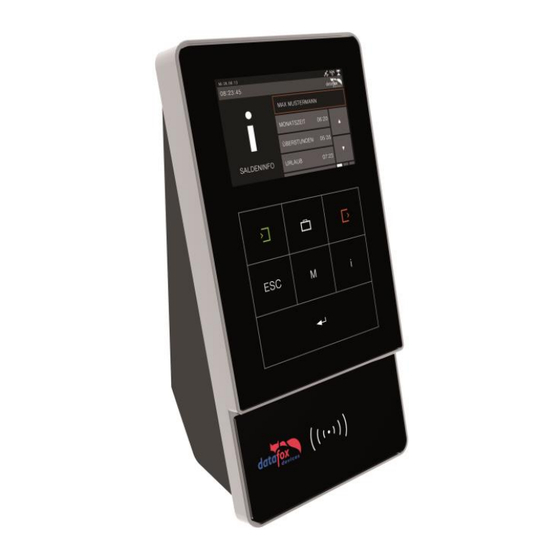
Page 21: Operation And Display Elements Of The Evo 4.3
5.2. Operation and display elements of the Evo 4.3 5.2.1. Composition and Operation The terminal has a capacitive touch. When displaying lists or submenus, this touchpad is selected. Scroll up and down. If arrow keys on the lower part of the touch are stored, these must be used to select in the list. -
Page 22: Operation With Gesture Control For Evo 4.3
5.2.2. Operation with gesture control for EVO 4.3 The world of smartphones and tablets inspire all users of such devices. This operating convenience has also been introduced at Datafox. Now you can scroll through the display by "Wipe". This functionality is available here: scroll in Bios menu List display / menu display "scrolling"... -
Page 23: Display Setup And Bios Of The Evo 4.3
5.2.3. Display setup and bios of the Evo 4.3 5.2.3.1. Structure display "Normal display" Texts according to Setup Number of records Communication status of the main communication Field for customer logo Display and list box Date Time corresponds to the system time of the device, which is also used for the data records. -
Page 24: Structure Display Evo 4.3 "In The Bios Menu
5.2.3.2. Structure Display EVO 4.3 "in the Bios menu The bios menu is accessed by pressing the button at the same time „ESC“ und „Enter“. If in the Setup configured a password, you can edit/enter here. 1 display in the bios menu:... - Page 25 Menu -> general information Here you can test to read the badge For selection, just tap. Manual Datafox Evo 4.3 Page 19 Date: 27.12.2017 V 04.03.09.XX...
- Page 26 5 cm distance between. Layout: Here you can see the defined keys on the touchscreen such as numbers or ESC function keys. See the capter: Touchconfiguration and displaydesign. Manual Datafox Evo 4.3 Page 20 Date: 27.12.2017 V 04.03.09.XX...
- Page 27 IP-adress, port and more. Setting the LAN parameters TCP/IP (page 1)_( DHCP E4:F7. MAC Adress, starts by the datafox devices ever with activate DHCP, automatic IP address assignment Actually ip-adress. When you use DHCP then can you not set the IP adress manually.
- Page 28 TCP/IP (set IP adress) Tap with the finger on the pos- sition were you need the cur- sor. Manual Datafox Evo 4.3 Page 22 Date: 27.12.2017 V 04.03.09.XX...
-
Page 29: Activate The Bootloader
In the menu User settings“ it is pos- sible restart the device. Confirm your cossing with a tipp (en- ter) on the display. All data and settings are kept. Manual Datafox Evo 4.3 Page 23 Date: 27.12.2017 V 04.03.09.XX... -
Page 30: Switch The Display Design
5.2.3.5. switch the display design The multifunctional terminal EVO 4.3 has 2 different display options. 1.) Display in the PZE-Master Style, This display layout serves to continue to use the known from the PZE Master IV operating concept. Also if PZE-Master and EVO 4.3 are used in paral- lel. -
Page 31: Create An New Display Design
To create an individual design, you need minimum the DatafoxStudioIV version: 04.03.06.XX. You find in the DatafoxStudioIV un- “Configuration >Display Desinger“, the poit to create an individual dis- play design. Manual Datafox Evo 4.3 Page 25 Date: 27.12.2017 V 04.03.09.XX... -
Page 32: Key And The Combinations
„Touch“ or slide with the finger over the display Assyme an chossed list entry ENTER-button Abbord an action ESC-button Chump in the main menu ESC-button Manual Datafox Evo 4.3 Page 26 Date: 27.12.2017 V 04.03.09.XX... -
Page 33: Displaydesigner
For the devices AE-MasterIV V4, PZE-MasterIV V4 and PZE-MasterIV Basic V4 is the Designer only usable for color display. With the Display-Designer, Datafox offers the possibility for partners and users to customize the display according to your requirements. But due to the necessary operating sequences, this cannot be a completely free design, but things like headlines, menu structures and footers have to be guar- anteed. -
Page 34: Color Setting For The Display
The device is delivery in the default „PZE“-design. This design is also set as de- fault when you first create a Function Key’s new theme in Display Designer. are not displayed in the default setting. Manual Datafox Evo 4.3 Page 28 Date: 27.12.2017 V 04.03.09.XX... -
Page 35: Display Function Buttons On The Evo 4.3 / 2.8 Display
5.2.4.3. Display function buttons on the EVO 4.3 / 2.8 display By showing the function buttons from the setup, the number of buttons displayed in the display can be adjusted. Example: 5.2.4.4. Upload images for function buttons of EVO 4.3 / 2.8 Under this menu item "Key... -
Page 36: Design Examples In The Designer
With the installation of the DatafoxStudioIV you get several design examples for the devices. Click on the "Design Examples" button to open them. Datafox gradually extends the examples. If you have any suggestions or wishes, please let us know. Manual Datafox Evo 4.3 Page 30 Date: 27.12.2017 V 04.03.09.XX... -
Page 37: Configuration Of The Touch
Select "Add Touch Position" to create individual keys. With each click in the area that is allowed for keys, another key is add- Note: The size and position of the keys can be perfectly aligned based on the position in the table. Manual Datafox Evo 4.3 Page 31 Date: 27.12.2017 V 04.03.09.XX... -
Page 38: Key-Picture Adn Key Pad
5.2.5.2. Transfer the touchconfiguration The created configuration for the touch screen is saved in a ". dfk" file. You can enter these here and transfer them to the ter- minal. Manual Datafox Evo 4.3 Page 32 Date: 27.12.2017 V 04.03.09.XX... -
Page 39: Create An Cange The Keys
Shift+arrow right () greater height: Shift+arrow down () larger than two pages: plus button (+) smaller sideways: Shift+arrow left () small height: Shift+arrow up () small two pages: minus key (-) Manual Datafox Evo 4.3 Page 33 Date: 27.12.2017 V 04.03.09.XX... -
Page 40: Available Character Set In The Touch Field
The availability of the charac- ters for the touch layout has been extended: “ < > and letters A-Z This means that special characters and letters can also be entered with the touch screen. Manual Datafox Evo 4.3 Page 34 Date: 27.12.2017 V 04.03.09.XX... -
Page 41: Switch Collours Of The Backligth
Please adjust the colors to your needs. Help for the mixed colour: colour part of red part green part blue part white yellow turquoise orange pink green blue white Manual Datafox Evo 4.3 Page 35 Date: 27.12.2017 V 04.03.09.XX... -
Page 42: Switch Lighting Depending On The Result
Find by the list selection no en- try, then switch the backligt to: „Result: ESC“ Find the selection an entry, then switch the backligth to: „Result: OK“ Manual Datafox Evo 4.3 Page 36 Date: 27.12.2017 V 04.03.09.XX... -
Page 43: Installation Of The Evo 4.3 Terminal
5.4. Installation of the EVO 4.3 Terminal The wall mounting takes place by means of a wall bracket. This is attached to the wall via 3 attach- ment points. The terminal is mounted at the to. On the down site... -
Page 44: Connecting Of Evo 4.3
Connecting of EVO 4.3 5.5.1. Connecting plugs EVO 4.3 The Evo 4.3 have intergatet 7 modulplaces. On this places can you order different modules. You can choose the modules on the pricelist. Here see you an example with some different modules:... -
Page 45: Powersupply Of The Evo 4.3
5.5.2. Powersupply of the EVO 4.3 5.5.2.1. Powersupply The delivery power supply have 12V DC / 18 W. The terminal itself can be supplied with a supply voltage of 24 V DC. The power supply: Reverse polarity protected connector 5.5.2.2. -
Page 46: Modules For Devices Of Hardware V4
5.5.3. Modules for devices of hardware V4 5.5.3.1. Description of the various extension modules The Datafox devices of the generation V4 are particularly distinguished by the variable configuration of individual modules. Depending on the device, a certain number of module locations are available. - Page 47 You see here, in the IO-Box are Modulplaces usable. This can be indi- vidually fitted. Exceptions: Modulplace 8, only here TCP is possible. RS 485 for access control - maximum 4 Modules can be fitted. Manual Datafox Evo 4.3 Page 41 Date: 27.12.2017 V 04.03.09.XX...
-
Page 48: Read Out Important Module Information From The Device
5.5.3.3. Read out important module information from the device Click on: "Configuration -> Device Configuration BI- OS" Then click on "Status" thereafter Click "Read". Manual Datafox Evo 4.3 Page 42 Date: 27.12.2017 V 04.03.09.XX... - Page 49 Status of the digital outputs: Output 1 is continuous here from left to right. Analog inputs from left to right with respective currently applied voltage. Number of stored records in the device and memory used. Manual Datafox Evo 4.3 Page 43 Date: 27.12.2017 V 04.03.09.XX...
-
Page 50: Connection Of The Individual Modules
Analogeingänge, 4 mal analog IN - Analog inputs, 4 times analog IN common ground; GND / Ground + 0-10 V Signal 4 + 0-10 V Signal 3 + 0-10 V Signal 2 + 0-10 V Signal 1 Manual Datafox Evo 4.3 Page 44 Date: 27.12.2017 V 04.03.09.XX... -
Page 51: Mal Digital Out - 2 Times Digital Out
4 times digital IN Connectiom example (Connection of 4 contacts): e.g.: 4x digital in max. 30V 0 - 1,5 V Input logical 0 3,5 V - 30 V Input logical 1 Manual Datafox Evo 4.3 Page 45 Date: 27.12.2017 V 04.03.09.XX... -
Page 52: Bus Für Zk - Rs-485 Bus For Access Control
Furthermore, the connection for a digital input and output is available. The pin assignment looks as follows: How the individual access components are connected or wired, can be found in the chapter "Access control" Manual Datafox Evo 4.3 Page 46 Date: 27.12.2017 V 04.03.09.XX... -
Page 53: Communication Of Hardware V4 Devices
The type of communication depends on the device. All possible communications are listet in the device. Note: Datafox-devices are able to communicate encrypted. „DatafoxStudioIV“. Read more in the manual for the The switching of the communication can be done via : 1. -
Page 54: Automatic Dedected Conectet Usb To Pc
If the device is connected to a pc no other connections (for example Wi-Fi) will happen If the USB-cable is disconnected it will automatically switch to the configured main com- munication Manual Datafox Evo 4.3 Page 48 Date: 27.12.2017 V 04.03.09.XX... -
Page 55: Installing Usb Driver For Hardware V4 Devices
Follow the instructions on the screen: Caution: Only use the driver wich are delivered with the device! Note: If you have DatafoxStudioIV installed the USB-driver will already be installed on your Manual Datafox Evo 4.3 Page 49 Date: 27.12.2017 V 04.03.09.XX... -
Page 56: Comunication / Record Transfer Via Usb-Stick (Host)
Lists of access control can be transferred individually, operation lists must always be transmitted in complete form. All lists defined in the setup must also exist on the stick in the "List" directory. Manual Datafox Evo 4.3 Page 50 Date: 27.12.2017 V 04.03.09.XX... -
Page 57: Error Message By Using Usb-Stick (Host)
Error by checking the handle, the file is not open Error write protect Error by the record stucture Error duren the firmware update No USB stick Incorrect password No list Manual Datafox Evo 4.3 Page 51 Date: 27.12.2017 V 04.03.09.XX... -
Page 58: Communication Via Tcp / Ip
The LAN / WLAN configurations are saved in a file with the filename extension "*. df0". Here you now have the possibility to edit the file, load it into the Datafox device (upload) or read it from the device (download). -
Page 59: Communication Tcp / Ip Via Network-Cable
For devices with display, the IP address can also be entered directly on the device. Press ESC and ENTER simultaneously to enter the Bios menu of the device. More information can be found in the chapter „bios menu“. Manual Datafox Evo 4.3 Page 53 Date: 27.12.2017 V 04.03.09.XX... -
Page 60: Communication Tcp / Ip Via Wlan / Wifi
When setting the encryption AES or WEP, only one type is used at a time. The setting AES+WEP means for some access points that AES encryption is performed first and then additionally encrypted with WEP. In this case, only set AES. Manual Datafox Evo 4.3 Page 54 Date: 27.12.2017 V 04.03.09.XX... - Page 61 WLAN connection. The user therefore has no insight into the dial-in parameters at the various locations. Hint: With automatic selection of the configuration / location, the first attempt is always made to establish a connection with the default schema. Manual Datafox Evo 4.3 Page 55 Date: 27.12.2017 V 04.03.09.XX...
-
Page 62: Location Selection In The Bios Menu Wlan
Recommended setting We recommend the following setting: - WPA2 - AES - Shared/PSK Datafox uses the following access points internally for testing: - Longshine LCS-WA5-45 IEEE802.11g - WatchGuard XTM WEB UI - Longshine IEEE802.11n - TP-Link WR841N v6/v7 00000000 Setting Access-Point Setting StudioIV_WLAN-Device Manual Datafox Evo 4.3... -
Page 63: Communication Via Cellular Network (Gprs)
The antenna is located in the connection compartment of the device and can optional- ly be replaced by an external antenna if reception is bad. The SIM card is inserted via the connection compartment of the EVO 4.3. Einsetzen der SIM-Karte beim EVO 4.3 The SIM card must be inserted into the device in this position. -
Page 64: Communication State
Device is the encryption active, but not on the server battery is down, to disable Modem. impossible connect to the provider or bzw. Roaming impossible close connection Turn modem off Manual Datafox Evo 4.3 Page 58 Date: 27.12.2017 V 04.03.09.XX... -
Page 65: Communication Via Sms
5.6.7. Communication via SMS 5.6.7.1. Send a SMS With the EVO 4.3, it's possible to send an SMS. Condition for this is, an integrated GPRS-Modem (communication via Cellular Network). The main communication must be set on GSM or GPRS/GSM. To send an SMS you must use the Field Function “send SMS” in the device Setup. -
Page 66: Receive Sms
(default setting). Save you an empty Key, then receive the device every SMS. The last received SMS can you see in the Bios-Menu under „general information Bios (Menu)“. Manual Datafox Evo 4.3 Page 60 Date: 27.12.2017 V 04.03.09.XX... - Page 67 Connection to the server with the saved parameters in the „active mode“. b) and c) Connection on Port 8000 to the server (www.datafox.de/123.123.123.123). d) Connection to the server “www.datafox.de” and port “4711”. Manual Datafox Evo 4.3 Page 61...
- Page 68 Control a technical system and send a SMS in trouble: Is the level of regulation from the system not correct then gives a report via SMS. The Datafox MasterIV is here not the regulator. He gives only a report in trouble. If necessary, a procedure also can be done.
-
Page 69: Communication Via Rs485
BUS A BUS A Pin 15 - BUS B BUS B BUS B Pin 14 - BUS A Pin 1 - GND Pin 1 - GND Pin 7 - GND Manual Datafox Evo 4.3 Page 63 Date: 27.12.2017 V 04.03.09.XX... -
Page 70: Connection And Wirering Of The Accesscontrol
When adding comments, you have to notice that in a comment line no field values can be given and that the comment line has to start with a semicolon. The table Reader.txt might look like this: RefLocation RefAction PinGeneral Manual Datafox Evo 4.3 Page 64 Date: 27.12.2017 V 04.03.09.XX... - Page 71 Online / offline after time-out is a combination. If the serv- er is unavailable, the terminal can decide on basis of its lists whether to grant access to a person or not. Manual Datafox Evo 4.3 Page 65 Date: 27.12.2017 V 04.03.09.XX...
- Page 72 (19.00) on all weekdays. The corresponding relay is at the door module with the bus number 2. Reader.txt RefLocation RefAction PinGeneral Time.txt Weekdays TimeEnd TimeEnd 10:00 12345 00:00 12345 16:00 00:00 1234567 07:00 19:00 Action.txt RefReader PortOut Elapse RefTime Manual Datafox Evo 4.3 Page 66 Date: 27.12.2017 V 04.03.09.XX...
-
Page 73: Description Of Tables For Access Control 2
Indicates the assigned time model. (0 = not used) During this time access is RefTime granted. Thus, also "‘half holidays"’ like New Year’s Eve can be realized. (Time) Table Holiday (setting blocking days like holidays or company holidays) Manual Datafox Evo 4.3 Page 67 Date: 27.12.2017 V 04.03.09.XX... -
Page 74: Access Control Ii With Phg-Modules
Table Action (list of all workable actions in the access control system; an action group, i.e. all ac- tions with the same action number, can switch several relays) 5.7.3. Access control II with PHG-Modules Manual Datafox Evo 4.3 Page 68 Date: 27.12.2017 V 04.03.09.XX... - Page 75 Mifare is supported. Here for 5 of the max. 6 keys can be used in the setup. Attention: Technical data for the PHG access modules can be found on the Datafox DVD or in our download area. Please note the power consumption of the modules and the voltage drop at long cable lengths.
-
Page 76: Connecting Of Phg-Reader
5.7.3.1. Connecting of PHG-reader In order to connect the PHG modules, please note the PHG documentation on the Datafox CD: <Datafox-Geräte- Datafox-Zutritt-Module PHG *.pdf> In the PHG documents for the single modules, the pin assignment and configuration via the DIP switches are described. - Page 77 I/O-Box RS485 I²C max. 1000 m max. 5 m floating relay contact Reader I/O-Box Power supply 12 V DC for reader C max. 5m ISTY 2x2x0,8 / – / Manual Datafox Evo 4.3 Page 71 Date: 27.12.2017 V 04.03.09.XX...
- Page 78 Power supply for door opener Bus Nr. 1 Siedle-access reader Wire plan for Siedle access reader: Power supply 12 V DC for reader max. 42V; 2A Power supply for door opener Manual Datafox Evo 4.3 Page 72 Date: 27.12.2017 V 04.03.09.XX...
- Page 79 5 Reader potential-free contact for door RS485 I²C max. 5 Reader potential-free contact for door more reader Last reader last reader end resistor max. 1000 m switch 7 -> on Manual Datafox Evo 4.3 Page 73 Date: 27.12.2017 V 04.03.09.XX...
- Page 80 – / ~ further reader In any case, a protection circuit should be integrated when connecting the door-opener. A fly back diode for DC and an RC element for AC. Manual Datafox Evo 4.3 Page 74 Date: 27.12.2017 V 04.03.09.XX...
- Page 81 Relais 2 normaly open free free digital in 2 Signal digital in 2 ground 1 und 2 ground U+ 8…..30V ST 1 Circuit diagram “S“ normaly open “G“ common “Ö“ normaly close Manual Datafox Evo 4.3 Page 75 Date: 27.12.2017 V 04.03.09.XX...
-
Page 82: Configuration
Manual Datafox Evo 4.3 Page 76 Date: 27.12.2017 V 04.03.09.XX... - Page 83 I C bus, is omitted. Corresponding reader table: RefLocation RefAction PinGeneral Description Master device Reader at RS485 (PHG) IO-Box at I C-Bus Reader at RS485 (LTM) IO-Box at I C-Bus Manual Datafox Evo 4.3 Page 77 Date: 27.12.2017 V 04.03.09.XX...
-
Page 84: Access Control Wiht Evo-Access Modules
Ambient temperature, Protection -20 ° C to +70 ° C, IP65 Transponder systems 125kHz Mifare Legic Hitag 1+2+S Mifare Classic Legic prime Unique EM4102 Mifare Desfire Legic advant Titan EM4450 Mifare Ultralight Manual Datafox Evo 4.3 Page 78 Date: 27.12.2017 V 04.03.09.XX... - Page 85 3, without terminate resistor 0-0-0-1-1 Connector for IO- modul Relay + digital in description Number. +10V bis +30V DC ! neu RS 485-Data „B“ DIP-switch RS 485-Data „A“ GND ground Manual Datafox Evo 4.3 Page 79 Date: 27.12.2017 V 04.03.09.XX...
-
Page 86: Connecting Of The Evo-Access Reader Examples
5.7.4.1. Connecting of the EVO-access reader examples Cable plan for one door, 1 Relay in the EVO 4.3: Bus Nr. 1 RS 485 ZK Bus-ID 1 TCP / IP (LAN) 12V vom Master Türöffner Relais 1 der ZK-Box Bus Nr. 1... -
Page 87: Access Control Ii With Evo-Zk-Plus-Reader
RGB colours. The control of the LED is con- trolled exclusively by the readers firmware. access denied = red - access permitted = green - Bios activated = blue - Manual Datafox Evo 4.3 Page 81 Date: 27.12.2017 V 04.03.09.XX... -
Page 88: Display For State Of Acces Control
5.7.5.4. Errormessage error communication The reader is in constant communi- cation with the master. If communication is interrupted, this is indicated by the text "Communi- cation error" on the reader. Manual Datafox Evo 4.3 Page 82 Date: 27.12.2017 V 04.03.09.XX... -
Page 89: Bios-Menu
The following information can be called up in the general con- figuration: - Installed firmware, serial number - Memory allocation for the image memory - Transponder test for the transponder configured in the mas- ter setup. Manual Datafox Evo 4.3 Page 83 Date: 27.12.2017 V 04.03.09.XX... -
Page 90: Display Configuration
The bus terminating resistor of 120 Ω is switched on or off in the bus configuration under "Terminating resistor". Note: If it is the last or only reader in the RS485 bus, the termi- nating resistor must be switched on. Manual Datafox Evo 4.3 Page 84 Date: 27.12.2017 V 04.03.09.XX... -
Page 91: Connection Of The Evo-Access Reader Plus
Diese Erweiterung sollte nicht im ungesicherten Bereich eingesetzt werden. Transponder Leseverfah- 125kHz Mifare Legic Hitag 1+2+S Mifare Classic Legic prime Unique EM4102 Mifare Desfire Legic advant Titan EM4450 Mifare Ultralight Manual Datafox Evo 4.3 Page 85 Date: 27.12.2017 V 04.03.09.XX... - Page 92 Verkabelungsplan für 1 Türen, 1 Relais in dem EVO 4.3: Bus Nr. 1 10-30V DC TCP / IP (LAN) RS 485 ZK Bus-ID 1 Türöffner Relais 1 des Master Gerätes Entsprechende Reader Tabelle, Beispiel: ZM / Bus-ID TM (Busadresse) RefLocation...
- Page 93 Verkabelungsplan für 3 Türen, 3 Relais in dem EVO 4.3: Spannungsversorgung Bus Nr. 1 12 – 30V DC pro Leser 500mA RS 485 ZK TCP / IP (LAN) max.2,5 m bis Abzweig Türöffner Relais 1 Bus Nr. 2 Spannungsversorgung für Türöffner.
- Page 94 Verdrahtungsplan für 3 Türen, 3 Relais in dem EVO 4.3: Spannungsversorgung 12 – 30 V Bus Nr. 1 - Spannung für Türöffner max. 2,5m Bus Nr. 2 max. 2,5m Bus Nr. 3 max. 2,5m weitere Leser möglich Manual Datafox Evo 4.3 Page 88 Date: 27.12.2017 V 04.03.09.XX...
-
Page 95: Access Control With Ts-Readers
A connecting diagram and a description of the commands for the activation are included. Note: The single modules are connected to a bus. DIP switch 5 sets whether the modules are to communicate via RS232 or RS485. Manual Datafox Evo 4.3 Page 89 Date: 27.12.2017 V 04.03.09.XX... -
Page 96: Installation Variants
Installation Variants A Door without a Separate Reader The EVO 4.3 is access scanner, access master and door-opener at the same time. This solution should only be used in protected areas so that the door opening relay cannot be manipulated. - Page 97 The door opening relay is in the PZE- MasterIV and thus installed in the protected area. The access identification captured by the reader is transferred to the EVO 4.3 and analyzed by it. If access is permitted, the door is opened via the relay in the .
- Page 98 RS232 connection max. 15 m Relay for door Door control Wire plan: Reader (L) Art-Nr.:106020 Door control max. 30V 2A door opener Reader (L) Art-Nr.:106020 Door control max. 30V 2A door opener Manual Datafox Evo 4.3 Page 92 Date: 27.12.2017 V 04.03.09.XX...
- Page 99 Door monitoring ext. max. 30V 2A Door opener Reader and door modul (LTM) Art-Nr.:106030 Button, for door opening from inside Door – contact Door monitoring ext. max. 30V 2A Door opener Manual Datafox Evo 4.3 Page 93 Date: 27.12.2017 V 04.03.09.XX...
- Page 100 Reader and relay on RS485 (LTM) Reader on RS232 (L) Reader and relay on RS485 (LTM) Reader on RS232 (L) Reader and relay on RS485 (LTM) Reader on RS232 (L) Manual Datafox Evo 4.3 Page 94 Date: 27.12.2017 V 04.03.09.XX...
- Page 101 At closed door contact ca. 15 mA are used up at 12 V = 0.18 Watt. This means a con- sumption of ca. 1.6 kWh per year. Manual Datafox Evo 4.3 Page 95 Date: 27.12.2017 V 04.03.09.XX...
-
Page 102: Connecting The Ts-Series Access Reader
DIP switch 1 in position "ON" and switches 2 - 5 in position "‘OFF"’ stand for bus number "1". DIP switches 1 and 2 in position "ON" and switches 3 - 5 in position "OFF" stand for bus no. "3". Manual Datafox Evo 4.3 Page 96... - Page 103 Door opener Combination module (LTM) Art-Nr.: 106030 Tür Kontakt ext. max 30V 2A Door opener Reader module (L) Art-Nr.:106020 More modules are possible. Tür Kontakt ext. max 30V 2A Door opener Manual Datafox Evo 4.3 Page 97 Date: 27.12.2017 V 04.03.09.XX...
- Page 104 OFF Termination for RS485 bus (0= termination off, 1= termination on) 120Ω Example bus address register: Address Bit 0 Bit 1 Bit 2 Bit 3 Bit 4 DIP switch folder. Manual Datafox Evo 4.3 Page 98 Date: 27.12.2017 V 04.03.09.XX...
-
Page 105: Calculation For The Power Supply Of Access Modules
RS485 network for access control. The voltage drop in the whole bus must not exceed 4 V. Please note that if you use a Datafox device power supply unit as voltage source, 16 modules at most (8 in the RS485 bus and 8 via RS232 stub line) can be fed. -
Page 106: Cable Length And Cable Cross Section For Access Wirering
12V: • mm Cable cross section: • mm Cable cross section: power supply reader with separated power supply 24V: • mm Cable cross section: • mm Cable cross section: Manual Datafox Evo 4.3 Page 100 Date: 27.12.2017 V 04.03.09.XX... -
Page 107: Online Funktions For The Access Control
With the anser from the server you are able to perform specific actions with the access readers The following examples will give you an insight in what is possible with the functions and actions. All parameters correspond the online functions with the dll. Manual Datafox Evo 4.3 Page 101 Date: 27.12.2017 V 04.03.09.XX... - Page 108 For this, the new keywords "module" and "master" were implemented. These must be used togeth- er, replacing the keyword "access". Attention: The order “access->mask->typ->duration” or master->module->mask->typ- >duration must be strictly adhered to. status=ok&checksum=2482&access=010&mask=5&type=1&duration=2 status=ok&checksum=2482&master=1&module=010&mask=5&type=1&duration=2 Manual Datafox Evo 4.3 Page 102 Date: 27.12.2017 V 04.03.09.XX...
- Page 109 You can also perform multiple actions on the access control in one response. However, the total length of the response must not exceed 254 characters. Attention: A automated switch between online and offline mode is not possible in http mode Manual Datafox Evo 4.3 Page 103 Date: 27.12.2017 V 04.03.09.XX...
-
Page 110: Online Via Dll Connection
LEDs. More dll functions are documented in the “Datafox SDK” on our website http://www.datafox.de/software- de.html?file=tl_files/Datafox_Devices/Downloads_Geraete_Zubehoer/MasterIV-... -
Page 111: Function Extention For Access Control Ii
All readings of RFID on this reader make all actions in the table “action“, with the ID 3000. Tabelle Time Weekdays TimeStart TimeEnd Description text 1234567 00:01 23:59 24houers opening possible 1234567 07:00 16:00 Time for special action Manual Datafox Evo 4.3 Page 105 Date: 27.12.2017 V 04.03.09.XX... - Page 112 Menace ActiveStart ActiveEnd Active Description 1111 2005-01-01 2015-12-31 Master of Garage 2222 2005-01-01 2015-12-31 Skilled workers 3333 2005-01-01 2015-12-31 Facility manager Facility manager second RFID-chip, 4444 2005-01-01 2015-12-31 only for closing the door Manual Datafox Evo 4.3 Page 106 Date: 27.12.2017 V 04.03.09.XX...
- Page 113 Then tenant use the transponder to give only the switch for his floor free. In cabin of the elevator is install the RFID-reader. The Datafox-Device is on the top of the cabin. - RS485 Bus to the reader in the cabin...
- Page 114 2005-01-01 2099-12-31 floor Tenant of an apartment on the 1102 2005-01-01 2099-12-31 floor 1 and 2 Tenant of an apartment on the 1104 2005-01-01 2099-12-31 floor 1, 2 and 3 Manual Datafox Evo 4.3 Page 108 Date: 27.12.2017 V 04.03.09.XX...
-
Page 115: Description Of The Table „Action2
Would you like to continue working with the "action" table, the table "Action 2" may not be transferred to the device. A table "Action 2" has already been transferred to the device, it must be cleared by load- ing a new setup. Manual Datafox Evo 4.3 Page 109 Date: 27.12.2017 V 04.03.09.XX... -
Page 116: State Message Off Access Control
6 is low (Off). 56 # digital output 6 is HIGH.(On). 57 # digital output 6 is for the time ELAPSE, HIGH. for new devices hardware version 4 Manual Datafox Evo 4.3 Page 110 Date: 27.12.2017 V 04.03.09.XX... - Page 117 12 isLow 171# digital input 12 is HIGH _____ ____continuously until: 210# digital input 32 is Low 211# digital input 32 is HIGH for new devices hardware version 4 Manual Datafox Evo 4.3 Page 111 Date: 27.12.2017 V 04.03.09.XX...
- Page 118 1 alarm-input 2 alarm-input 3 alarm-input 4 alarm-input 1 alarm-input 6 220# alarm-input 7 221# alarm-input 8 _______ _____ continuously until: 245# alarm-input 32 for new devices hardware version 4 Manual Datafox Evo 4.3 Page 112 Date: 27.12.2017 V 04.03.09.XX...
- Page 119 State message off access control in a record: Note: Do you want see the status from accses control, to coose this settigs in the Setup. Manual Datafox Evo 4.3 Page 113 Date: 27.12.2017 V 04.03.09.XX...
-
Page 120: Funkcionfor Access Control U&Z (Locking Cylinders)
The electronic locking systems read an RFID chip / card and transmit the read information to Data- fox access control. The Datafox access control then decides on the basis of the access logic wheth- er the door is opened or not. - Page 121 12- 20 V + / 0 V - / ~ function B – RS 485 A – RS 485 operating voltage 0 V + / ~ 12- 20 V - / ~ Manual Datafox Evo 4.3 Page 115 Date: 27.12.2017 V 04.03.09.XX...
-
Page 122: First Start With Locking Cylinders
2nd) The knob module is mounted in the cylinder housing by inserting and simultaneously rotating it.(A+B) 3) To reset the disassembly mode, hold the disassembly card or an authorised transponder in front of the knob module.(C) Manual Datafox Evo 4.3 Page 116 Date: 27.12.2017 V 04.03.09.XX... -
Page 123: Set Up The Wireless Network For Cylinder
Teach out: The cylinder is removed from the FSM and can be taught in to another FSM. Teach-in: To connect a radio lock cylinder to the FSM (the radio lock cylinder then only communicates with this FSM) Manual Datafox Evo 4.3 Page 117 Date: 27.12.2017 V 04.03.09.XX... -
Page 124: Battery State And Live Time
Battery status of the radio lock cylinders in phase 1 Battery status of the radio lock cylinders in phase 2 Battery status of the radio lock cylinders in phase 3 (empty) Radio lock cylinder set to battery change mode Manual Datafox Evo 4.3 Page 118 Date: 27.12.2017 V 04.03.09.XX... -
Page 125: Change The Access Control Master Id And Nob Active Time
FSM is established and the connection remains active as long as the Knob Active Time is active. Useful values are between 2 and 10 seconds. By default, this time is set to 3 seconds. Manual Datafox Evo 4.3 Page 119 Date: 27.12.2017 V 04.03.09.XX... -
Page 126: Optische Und Akustische Signale Des U&Z Schließzylinders
(out of range) short short = = red flashing red lights up = = green flashing green lights up = long low tone = short beep Manual Datafox Evo 4.3 Page 120 Date: 27.12.2017 V 04.03.09.XX... -
Page 127: Unterstützte Transponderverfahren Und Einschränkungen
- read UID - Read file (max. 220Byte) Not supported is - Random UID (Read true UID at Random UID badges) Legic Prime and Legic Advant currently no restrictions are known. Manual Datafox Evo 4.3 Page 121 Date: 27.12.2017 V 04.03.09.XX... -
Page 128: Rfid Reader
For reading a transponder you must hold it in front of the device. The reading area is marked with the corresponding icon. The following transponder readers can be built-in the EVO 4.3 : EVO 4.3 with 125 kHz: Unique EM4102, Hitag1, Hitag2, HitagS, Hewi EM4450 LRW 8 cm R/W (LeseReichWeite “Read range”... -
Page 129: Data On Card
3031323334353637383941424344454630 …… 6987986 Franz Zufall The terminal stores where the data is written to the ID card (e.g. segment) Doors with electronic locking cylinder or similar. Current authorization yes / no Manual Datafox Evo 4.3 Page 123 Date: 27.12.2017 V 04.03.09.XX... -
Page 130: Settings For Using Dataoncard
When importing via the DLL, the data needs to be passed on as binary data. Using the DFC GetField, DFC GetField list functions, you are working with strings, while the firm- ware converts the hexstrings to and from the binary data. Manual Datafox Evo 4.3 Page 124 Date: 27.12.2017 V 04.03.09.XX... - Page 131 1. ) RFID Configurations for the RFID reader The transponder configuration for the reading can be freely selected. However, firstly it needs to be defined in the basic transponder settings. Manual Datafox Evo 4.3 Page 125 Date: 27.12.2017 V 04.03.09.XX...
- Page 132 Please note: First, complete the transponder configuration, then create the list with the binary field and finally parameterize the field function Data on Card. Manual Datafox Evo 4.3 Page 126 Date: 27.12.2017 V 04.03.09.XX...
- Page 133 0x30, 0x31, 0x32, 0x33, 0x34 …… Please note: When a 3-tone sequence is signaled, the Data-On-Card option is not available on this de- vice. The option has to be purchased afterwards. Manual Datafox Evo 4.3 Page 127 Date: 27.12.2017 V 04.03.09.XX...
-
Page 134: Dataoncard On The Access Control Reader
Only one access control reader (ZK) can be connected to the bus at any time. Dip switch 1 and the termination of the bus must be set to "ON" (Bus address 1). Manual Datafox Evo 4.3 Page 128 Date: 27.12.2017 V 04.03.09.XX... -
Page 135: Dataoncard An A Aceess Control Reader - Wirering
ZK-Knoten Wireringplan for EVO-access reader with using DataOnCard: EVO-access-reader connector ZK-Knoten Wireringplan for PHG-access reader with using DataOnCard: RS 485 bus line up to 500m in a twisted pair cable Manual Datafox Evo 4.3 Page 129 Date: 27.12.2017 V 04.03.09.XX... -
Page 136: Barcode Reader
5.10. Barcode Reader You can connect any barcode reader with a RS232 port to the EVO 4.3. Observe the following pin assignment of the RS232 interface. 12VDC RS232 Function Description Modulplace RS 232 Here an ex- Mini-DIN M004 ample on... - Page 137 Cable attachment of the barcode reader: Place the cable of the bar- code reader in the wall bracket approximately in this way or fix the cable with a cable tie. Manual Datafox Evo 4.3 Page 131 Date: 27.12.2017 V 04.03.09.XX...
-
Page 138: Finger Scanner
In no case may be components on the finger, which have an abrasive effect. These use the protective layer of the line sensor and thus significantly reduce the service life. Manual Datafox Evo 4.3 Page 132 Date: 27.12.2017 V 04.03.09.XX... -
Page 139: General Infomation
The behavior must be checked in each individual case, since it is very dependent on the group of people. In such cases, one should switch to another finger, because not every human finger is suitable for the Minutien method. Manual Datafox Evo 4.3 Page 133 Date: 27.12.2017 V 04.03.09.XX... -
Page 140: Teach-In
M. Mustermann 05597861113494 M. Musterfrau Step 2 Scan finger Step 3 PID and finger characteristics to combinate finger characteristics Template Step 4 Save Template on Biokey-Module on Mifare Transponder on Server Manual Datafox Evo 4.3 Page 134 Date: 27.12.2017 V 04.03.09.XX... -
Page 141: Procedure
(scanned) finger. The fingerprint module transfers PID and validity to the terminal. The task in the terminal for the fingerprint triggers an input sequence and access control - if defined in the setup. Manual Datafox Evo 4.3 Page 135 Date: 27.12.2017 V 04.03.09.XX... -
Page 142: Process Variants
2.) Delete template from fingerprint module or 1.) Determine PID (read from ID card or via list selection) 2.) Delete template from fingerprint module Deleting a template from a fingerprint module by verification Manual Datafox Evo 4.3 Page 136 Date: 27.12.2017 V 04.03.09.XX... -
Page 143: Technical Data Of The Fingerprint Module
Experience shows that not for all employees the fingers can be recorded in sufficient quality. o Depends on the state of the fingers. For those persons the ID card or PIN has to be recorded. Manual Datafox Evo 4.3 Page 137... -
Page 144: Tecnical Data Evo 4.3 Terminal
-20 ° C to +70 ° C (Power Supply -20 ° C to +60 ° C) Protection IP 65 front side, IP54 complete Software Configuration program Setup program (Datafox-Studio) to configure without programming effort Communication tools http, DLL or C source code for inclusion in the application Module extensions For the extension to a variety of functions such as communication, inputs / outputs, sensors, ... -
Page 145: Communication Modules
RS485 Width 20mm RS485 connection for the access reader, relay modules, ... power supply from 1 external reader when using Datafox power supplies with Access Control-IO Width 20mm 1 relay changeover, 42 V AC, DC 60 V, 2 A, max. 60 W; 1 digital input for monitoring door, ... -
Page 146: Index
Evo 4.3 Terminal 143 Index USB 47, 49 Access with PHG reader 72 Bios 18 Device 13 DHCP 18 DIP switches ZK 99 FAQ 144 For you Safty 1 GPRS 58 graphic on display 27 Holiday control ZK 65...
Need help?
Do you have a question about the Evo 4.3 and is the answer not in the manual?
Questions and answers