Table of Contents
Advertisement
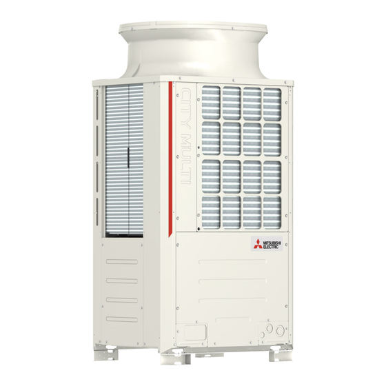
OUTDOOR UNIT
PUHY-P-YNW-A(-BS)
PUHY-EP-YNW-A(-BS)
INSTALLATION MANUAL
For safe and correct use, please read this installation manual thoroughly before installing the air-conditioner unit.
INSTALLATIONSHANDBUCH
Zum sicheren und ordnungsgemäßen Gebrauch der Klimageräte das Installationshandbuch gründlich durchlesen.
MANUEL D'INSTALLATION
Veuillez lire le manuel d'installation en entier avant d'installer ce climatiseur pour éviter tout accident et vous assurer d'une utilisation correcte.
MANUAL DE INSTALACIÓN
Para un uso seguro y correcto, lea detalladamente este manual de instalación antes de montar la unidad de aire acondicionado.
MANUALE DI INSTALLAZIONE
Per un uso sicuro e corretto, leggere attentamente questo manuale di installazione prima di installare il condizionatore d'aria.
INSTALLATIEHANDLEIDING
Voor een veilig en juist gebruik moet u deze installatiehandleiding grondig doorlezen voordat u de airconditioner installeert.
MANUAL DE INSTALAÇÃO
Para segurança e utilização correctas, leia atentamente este manual de instalação antes de instalar a unidade de ar condicionado.
NÁVOD NA INŠTALÁCIU
INSTALLATIONSHANDBOK
INSTALLATIONSMANUAL
Læs venligst denne installationsmanual grundigt, før De installerer airconditionanlægget, af hensyn til sikker og korrekt anvendelse.
INSTALLASJONSHÅNDBOK
For sikker og riktig bruk, skal du lese denne installasjonshåndboken nøye før du installerer klimaanlegget.
For use with R410A
Advertisement
Table of Contents

Related Manuals for Mitsubishi Electric City Multi PUHY-P200YNW-A


Summary of Contents for Mitsubishi Electric City Multi PUHY-P200YNW-A
- Page 1 OUTDOOR UNIT PUHY-P-YNW-A(-BS) For use with R410A PUHY-EP-YNW-A(-BS) INSTALLATION MANUAL For safe and correct use, please read this installation manual thoroughly before installing the air-conditioner unit. INSTALLATIONSHANDBUCH Zum sicheren und ordnungsgemäßen Gebrauch der Klimageräte das Installationshandbuch gründlich durchlesen. MANUEL D’INSTALLATION Veuillez lire le manuel d’installation en entier avant d’installer ce climatiseur pour éviter tout accident et vous assurer d’une utilisation correcte.
-
Page 3: Table Of Contents
CONTENTS 1. Safety precautions ················································································ 2 1-1. General precautions....................... 2 1-2. Precautions for transporting the unit ..................3 1-3. Precautions for unit installation ....................4 1-4. Precautions for piping work....................4 1-5. Precautions for electrical wiring ..................... 5 1-6. Precautions for relocating or repairing the unit ..............5 1-7. -
Page 4: Safety Precautions
- Operating the unit with a safety device whose settings have been changed may result in bursting, fire, or explosion. - Using safety devices other than those specified by Mitsubishi Electric may result in bursting, fire, or explosion. Do not alter or modify the unit. -
Page 5: Precautions For Transporting The Unit
Do not touch the refrigerant pipes and refrigerant line components with bare hands during and immediately after operation. - The refrigerant in the pipes will be very hot or very cold, resulting in frostbite or burns. Do not touch the electrical parts with bare hands during and immediately after operation. - Doing so may result in burns. -
Page 6: Precautions For Unit Installation
1-3. Precautions for unit installation Do not install the unit where combustible gas may leak. - If combustible gas accumulates around the unit, fire or explosion may result. Do not allow children to play with the packing materials. - Suffocation or serious injury may result. Cut up the packing materials before disposal. -
Page 7: Precautions For Electrical Wiring
1-5. Precautions for electrical wiring Include some slack in the power cables. - Failure to do so may break or overheat the cables, resulting in smoke or fire. Connections must be made securely and without tension on the terminals. - Improperly connected cables may break, overheat, or cause smoke or fire. Tighten all terminal screws to the specified torque. -
Page 8: Additional Precautions
1-7. Additional precautions Do not turn off the power immediately after stopping operation. - Wait for at least five minutes after the unit has stopped before turning off the power. Failure to do so may result in drain water leakage or the mechanical failure of sensitive parts. The unit must be periodically inspected by a dealer or qualified personnel. - Page 9 Use a vacuum pump with a check valve. - If the vacuum pump oil flows back into the refrigerant lines, the refrigerant oil may deteriorate and the compressor may malfunction. Keep tools clean. - If dust, dirt, or water accumulates on the charging hose or the flare processing tool, the refrigerant will deteriorate and the compressor will malfunction.
-
Page 10: About The Product
2. About the product ・The outdoor unit described in this manual is air-conditioning equipment that is designed only for human comfort. ・The numeric values in the unit model name (e.g., PUHY-P***YNW-A, PUHY-EP***YNW-A) indicate the capacity index of the unit. ・This unit uses R410A refrigerant. 3. - Page 11 (2) EP models Outdoor unit model Combination of outdoor units PUHY-EP200YNW-A(-BS) PUHY-EP250YNW-A(-BS) PUHY-EP300YNW-A(-BS) PUHY-EP350YNW-A(-BS) PUHY-EP400YNW-A(-BS) PUHY-EP450YNW-A(-BS) PUHY-EP500YNW-A(-BS) PUHY-EP400YSNW-A(-BS) PUHY-EP200YNW-A(-BS) PUHY-EP200YNW-A(-BS) PUHY-EP450YSNW-A(-BS) PUHY-EP250YNW-A(-BS) PUHY-EP200YNW-A(-BS) PUHY-EP500YSNW-A(-BS) PUHY-EP250YNW-A(-BS) PUHY-EP250YNW-A(-BS) PUHY-EP550YSNW-A(-BS) PUHY-EP300YNW-A(-BS) PUHY-EP250YNW-A(-BS) PUHY-EP600YSNW-A(-BS) PUHY-EP300YNW-A(-BS) PUHY-EP300YNW-A(-BS) PUHY-EP650YSNW-A(-BS) PUHY-EP400YNW-A(-BS) PUHY-EP250YNW-A(-BS) PUHY-EP700YSNW-A(-BS) PUHY-EP350YNW-A(-BS) PUHY-EP350YNW-A(-BS) PUHY-EP750YSNW-A(-BS) PUHY-EP400YNW-A(-BS) PUHY-EP350YNW-A(-BS) PUHY-EP800YSNW-A(-BS) PUHY-EP450YNW-A(-BS)
-
Page 12: Specifications
4. Specifications (1) P models Model PUHY-P200YNW-A PUHY-P250YNW-A PUHY-P300YNW-A PUHY-P350YNW-A PUHY-P400YNW-A PUHY-P450YNW-A Cooling 4.24 5.78 7.66 9.87 11.47 12.22 Power input Heating 4.58 6.04 7.86 10.51 13.40 13.42 Sound pressure level (50/60 Hz) 58.0 dB <A> 60.0 dB <A> 61.0 dB <A> 62.0 dB <A>... - Page 13 Model PUHY-P1250YSNW-A PUHY-P1300YSNW-A PUHY-P1350YSNW-A Cooling 36.17 37.24 37.78 Power input Heating 41.40 41.55 41.40 Sound pressure level (50/60 Hz) 70.0 dB <A> 70.0 dB <A> 70.5 dB <A> External static pressure 0 Pa* Total capacity 50% to 130%* Indoor unit Model 15 to 250 Quantity...
- Page 14 Model PUHY-EP950YSNW-A PUHY-EP1000YSNW-A PUHY-EP1050YSNW-A PUHY-EP1100YSNW-A PUHY-EP1150YSNW-A PUHY-EP1200YSNW-A Cooling 23.62 25.33 27.05 28.56 30.56 32.58 Power input Heating 25.79 28.70 31.26 33.00 35.60 38.34 Sound pressure level (50/60 Hz) 66.0 dB <A> 68.0 dB <A> 68.5 dB <A> 68.5 dB <A> 69.0 dB <A>...
-
Page 15: Package Contents
5. Package contents The table below lists all the parts and their quantities included in the package. (1) P models Tie band P200 P250 P300 P350 P400 P450 P500 (2) EP models Tie band EP200 EP250 EP300 EP350 EP400 EP450 EP500 KJ79F137H01 GB-13... -
Page 16: Transporting The Unit
6. Transporting the unit When lifting the unit, pass the slings through the four designated sling holes. - Improper lifting will cause the unit to topple or fall, resulting in serious injury. ・Always use two slings to lift up the unit. Each sling must be at least 8 m (26 ft) long and must be able to support the weight of the unit. -
Page 17: Installation Location
7. Installation location Do not install the unit where combustible gas may leak. - If combustible gas accumulates around the unit, fire or explosion may result. ・Provide sufficient space around the unit for effective operation, efficient air movement, and ease of access for maintenance. -
Page 18: Multiple Unit Installation
(3) When there are overhead obstacles Air outlet guide (not supplied) 7-2. Multiple unit installation ・When installing multiple units, make sure to take into consideration factors such as providing enough space for people to pass through, ample space between blocks of units, and sufficient space for airflow. (The areas marked with Ⓐ... - Page 19 (3) Combination of face-to-face and side-by-side installations When there are walls in the front and rear of the block of units Ⓐ Unit height h2’ Unit height Ⓐ L2’ Required minimum distance [mm (in)] L2 (Rear) L2' (Rear) L4 (Between) 300 (11-13/16) + h2 300 (11-13/16) + h2' 900 (35-7/16)
-
Page 20: Foundation Work
8. Foundation work Install the unit in accordance with the instructions to minimize the risk of damage from earthquakes and strong winds. - Improper installation will cause the unit to topple, resulting in serious injury. The unit must be securely installed on a structure that can sustain its weight. - Failure to do so will cause the unit to fall, resulting in serious injury. - Page 21 ・To remove the detachable legs on site, unscrew the screws shown in the figure below. If the unit leg coating is damaged when the detachable leg is removed, repair the coating on site. Ⓐ Screws Ⓐ Ⓐ ・In abnormally harsh environments such as cold and/or windy areas, sufficient countermeasures to guard against excessive wind and snow should be taken to ensure the unit’s correct operation.
-
Page 22: Refrigerant Piping Work
- It may also be in violation of applicable laws. - MITSUBISHI ELECTRIC CORPORATION cannot be held responsible for malfunctions or accidents resulting from the use of the wrong type of refrigerant. - Page 23 ・The pipe from multiple outdoor units must be installed so that oil will not accumulate in the pipe under certain conditions. Refer to the figures below for details. * Small dots in the figures indicate branching points. Ⓐ To indoor units (1) The pipe from the outdoor units must be inclined downward to the indoor unit side.
-
Page 24: Pipe Selection
・Restriction on installing the indoor unit twinning kit CMY-Y202S-G2 or CMY-Y302S-G2 on the gas piping To outdoor unit or heat source unit To indoor unit (branched pipe) - The indoor unit twinning kit on the gas piping must be installed horizontally (as shown in the figure at left below) or with the branched pipes facing up (as shown in the figure at right below). -
Page 25: Twinning Kit Selection
9-3. Twinning kit selection 9-3-1. Indoor unit twinning kit Select a proper indoor unit twinning kit (sold separately) based on the total capacity of the downstream indoor units, using the table below as a reference. Line branching Total capacity of downstream indoor units Kit model 200 or below CMY-Y102SS-G2... - Page 26 ・Example of pipe connection between outdoor units and indoor units P200 to P500YNW-A EP200 to EP500YNW-A Unit 1 Unit 1 Ⓐ Ⓐ Ⓕ Ⓑ Ⓓ Ⓑ Ⓒ Ⓒ Ⓒ Ⓒ Ⓒ Ⓒ Ⓒ Ⓒ Ⓒ Ⓒ P400 to P900YSNW-A EP550 to EP900YSNW-A Unit 1 Unit 2 Unit 1...
- Page 27 (1) P models Pipes A, A [mm] Combination unit Pipe A Pipe A Pipe A Pipe A Pipe A Unit model Unit 1 Unit 2 Unit 3 Liquid Liquid Liquid Liquid Liquid P200YNW-A ø9.52 ø22.2 P250YNW-A ø9.52 * ø22.2 P300YNW-A ø9.52 * ø22.2 P350YNW-A...
- Page 28 (2) EP models Pipes A, A [mm] Combination unit Pipe A Pipe A Pipe A Pipe A Pipe A Unit model Unit 1 Unit 2 Unit 3 Liquid Liquid Liquid Liquid Liquid EP200YNW-A ø9.52 ø22.2 EP250YNW-A ø9.52 * ø22.2 EP300YNW-A ø9.52 * ø28.58 EP350YNW-A...
- Page 29 Pipes A, A [in] Combination unit Pipe A Pipe A Pipe A Pipe A Pipe A Unit model Unit 1 Unit 2 Unit 3 Liquid Liquid Liquid Liquid Liquid EP200YNW-A ø3/8 ø7/8 EP250YNW-A ø3/8 * ø7/8 EP300YNW-A ø3/8 * ø1-1/8 EP350YNW-A ø1/2 ø1-1/8...
-
Page 30: Piping Connections And Valve Operations
9-5. Piping connections and valve operations Before heating the brazed sections, remove the gas and oil that are trapped in the pipes. - Failure to do so may generate fire, resulting in serious injury. Ventilate the room while servicing the unit. - If the refrigerant leaks, oxygen deficiency may result. - Page 31 ・Do not use any commercially available anti-oxidizing agents since they may cause pipe corrosion and degrading of the refrigerant oil. Please contact Mitsubishi Electric for more details. ・Make sure that the pipes are not in contact with each other, unit panels, or base plates.
- Page 32 <Refrigerant piping connection examples> ・Obtain joints and elbows on site as necessary according to the pipe diameter, and connect the pipes as shown in the figures below. (1) When routing the pipes through the front of the unit <A> <B> Ⓐ...
- Page 33 <Reference> Size of refrigerant pipes On-site piping [mm (in)] Service valve piping [mm (in)] Liquid Liquid P200 ø9.52 (ø3/8) ø9.52 (ø3/8) P250 ø12.7 (ø1/2) ø22.2 (ø7/8) ø9.52 (ø3/8) ø9.52 (ø3/8) P300 *4*6 ø12.7 (ø1/2) P350 ø12.7 (ø1/2) ø12.7 (ø1/2) P400 ø15.88 (ø5/8) ø28.58 (ø1-1/8) ø28.58 (ø1-1/8)
-
Page 34: Air-Tightness Test
9-5-3. Sealing the openings around the pipes Seal all openings around pipes and wires to keep out small animals, rainwater, or snow. - Failure to do so may result in current leakage, electric shock, or damage to the unit. Ⓐ Example of closure materials (not supplied) Ⓑ... -
Page 35: Thermal Insulation For Pipes
9-7. Thermal insulation for pipes Insulate pipes to prevent condensation. - Condensation may collect and drip from the unit onto the ceiling or floor. Insulate the liquid and gas pipes separately with polyethylene foam insulation materials. Inadequate insulation may cause condensation to drip. Pipes in the ceiling are especially vulnerable to condensation and require adequate insulation. - Page 36 9-7-2. Insulation for the section of the pipe that goes through a wall (1) Inner wall (concealed) (2) Outer wall (3) Outer wall (exposed) Ⓓ Ⓔ Ⓐ Ⓑ Ⓒ Ⓑ Ⓐ Ⓑ Ⓗ (4) Floor (waterproof) (5) Rooftop pipe shaft (6) Protecting the penetrating parts in a fire limit zone or through a parting wall Ⓓ...
-
Page 37: Evacuation Of The System
9-8. Evacuation of the system Do not purge the air using refrigerant. Use a vacuum pump to evacuate the system. - Residual gas in the refrigerant lines will cause bursting of the pipes or an explosion. Use a vacuum pump with a check valve. - If the vacuum pump oil flows back into the refrigerant lines, the refrigerant oil may deteriorate and the compressor may malfunction. -
Page 38: Additional Refrigerant Charge
9-9. Additional refrigerant charge Charge refrigerant in a liquid state. - Charging refrigerant in the gaseous state will change the composition of the refrigerant and lead to a performance drop. Do not use a charging cylinder when charging refrigerant. - The use of a charging cylinder may change the composition of the refrigerant and lead to a performance drop. - Page 39 9-9-1. Calculation of the amount of additional refrigerant ・The amount of refrigerant to be added depends on the size and the total length of the liquid piping. ・Calculate the amount of refrigerant to be charged according to the formula below. ・Round up the calculation result to the nearest 0.1 kg (0.1 oz).
- Page 40 The total length of each liquid piping is as follows: ø12.7 total length: 40 (A) ø9.52 total length: 10 (B) + 15 (C) + 10 (D) + 10 (a) + 5 (b) + 10 (e) = 60 ø6.35 total length: 10 (c) + 10 (d) = 20 Therefore, when the piping length from the outdoor unit to the farthest indoor unit is longer than 30.5 m (100 ft), Amount of additional charge = (40 ×...
- Page 41 e : ø3/8; 32 ft The total length of each liquid piping is as follows: ø1/2 total length: 131 (A) ø3/8 total length: 32 (B) + 49 (C) + 32 (D) + 32 (a) + 16 (b) + 32 (e) = 193 ø1/4 total length: 32 (c) + 32 (d) = 64 Therefore, when the piping length from the outdoor unit to the farthest indoor unit is longer than 30.5 m (100 ft), Amount of additional charge = (131 ×...
-
Page 42: Electrical Work
10. Electrical work Electrical work must be performed by qualified personnel in accordance with local regulations and the instructions provided in this manual. Only use the specified cables and dedicated circuits. - Inadequate power source capacity or improper electrical work will result in electric shock, malfunction, or fire. - Page 43 ・Be sure to use the appropriate type of overcurrent breaker. Note that generated overcurrent may include some amount of direct current. ・Select the type of breaker for an inverter circuit as an earth leakage breaker. (Mitsubishi Electric NV-S series or its equivalent) ・The earth leakage breaker should be used in combination with a local switch.
- Page 44 Indoor unit Sample chart PLFY-VBM, PMFY-VBM, PEFY-VMS, PCFY-VKM, Type 1 18.6 6000 PKFY-VHM, PKFY-VKM, PFFY-VKM, PFFY-VLRMM Type 2 PEFY-VMA Type 3 PEFY-VMHS 13.8 SAMPLE Type 4 Indoor unit other than the above "C" is multiples of the tripping current at 0.01 s. Obtain the value of "C"...
-
Page 45: Control Cable Specifications
10-3. Control cable specifications ・Transmission cable Type 2-core shielded cable CVVS, CPEVS, or MVVS Size 1.25 mm (AWG 16), or ø1.2 mm or above Length Max. 200 m (656 ft) The maximum allowable length of transmission cables via outdoor units (both centralized control transmission cables and indoor-outdoor transmission cables) is 500 m (1640 ft) Remarks The maximum allowable length of transmission cables from the power supply unit to each outdoor unit or to the system... - Page 46 ・System configuration example * The numbers in the parentheses in the figures below indicate address numbers. (1) When ME remote controllers are connected Ⓐ Shielded cable Ⓑ Sub remote controller * Move the power jumper from Group 1 Group 3 Group 5 Ⓒ...
- Page 47 (2) When MA remote controllers are connected Ⓐ Shielded cable Ⓑ Sub remote controller Group 1 Group 3 Group 5 * Move the power jumper from Ⓒ System controller CN41 to CN40. * * SW5-1: ON * Ⓐ Ⓑ * Leave the power jumper connected to CN41.
-
Page 48: Wiring Connections In The Control Box
10-5. Wiring connections in the control box Connections must be made securely and without tension on the terminals. - Improperly connected cables may break, overheat, or cause smoke or fire. 10-5-1. Threading power cable through the knockout hole ・Open the front panel when performing wiring work. ・Punch out the knockout holes at the bottom of the front panel or base with a hammer. - Page 49 <Notice> ・Do not remove the ground wire that connects Main Box and Inverter Box. ・Install the transmission cable as shown in the figure above so that the cable is long enough for the Main Box to be moved for servicing. ・If there are any gaps around the power cable and transmission cable, please be sure to fill these in with a suitable material to prevent snow from entering, which may cause damage to the electrical parts, and to protect your hands from direct contact with cables.
- Page 50 10-5-2. Fixing the cables in place Route the cables as shown in the figures below. ・(E)P200 to 300 Inverter Box Main Box Power supply terminal block Cable strap Rubber bushing Transmission terminal block (for FAN cable) Rubber bushing Tie band (for main inverter connection (Supplied) wiring (200 V) and unit wiring...
- Page 51 Take the procedure below. ① Thread the power cable through the rubber bushing 1. (See * and * below.) ② Thread the unit wiring (sensor wiring) and the transmission cable through the rubber bushing 2. (See * and * below.) ③...
- Page 52 10-5-3. Connecting the cables PUHY-(E)P200 to 300YNW-A Ⓒ Ⓓ Ⓐ-1 Ⓐ-2 Ⓑ L1 L2 L3 N PUHY-(E)P350 to 500YNW-A Ⓐ Ⓒ Ⓓ Control box Ⓐ Ⓑ Ⓑ Power supply terminal block (TB1) Ⓒ L1 L2 L3 N Terminal block for indoor-outdoor transmission cable (TB3) Ⓓ...
-
Page 53: Address Setting
④ On the outdoor unit whose power jumper was moved from CN41 to CN40, short circuit the S terminal and the earth terminal. ⑤ Connect terminals M1 and M2 of the transmission terminal block on the indoor unit that has the lowest address in the group to the terminal block on the remote controller. -
Page 54: Test Run
11. Test run 11-1. Before a test run After the wiring work has been completed, measure the insulation resistance, and make - Failure to do so may result in electric leakage, malfunction, or fire. Turn on the power at least 12 hours before starting operation. Keep the power turned on throughout the operating season. -
Page 55: Function Setting
11-2. Function setting Make function settings by setting the dipswitches SW4, SW6, and SWP3 on the main board. Write down the switch settings on the electrical wiring diagram label on the control box front panel for future reference when the control box needs to be replaced. ・Take the following steps to make snow sensor settings. -
Page 56: Operation Characteristics In Relation To The Refrigerant Charge
11-3. Operation characteristics in relation to the refrigerant charge It is important to have a clear understanding of the characteristics of refrigerant and the operation characteristics of air conditioners before attempting to adjust the refrigerant charge in a given system. ・During cooling operation, the amount of refrigerant in the accumulator is the smallest when all indoor units are in operation. -
Page 57: Inspection And Maintenance
12. Inspection and maintenance Only qualified personnel must relocate or repair the unit. Do not attempt to disassemble or alter the unit. - Failure to do so will result in refrigerant leakage, water leakage, serious injury, electric shock, or fire. ・While the unit is turned on, the compressor will remain energized even when it is stopped. -
Page 58: Rating Plate Information
13. Rating plate information (1) P models Model P200YNW-A P250YNW-A P300YNW-A P350YNW-A P400YNW-A P450YNW-A P500YNW-A Unit combination – – – – – – – Refrigerant (R410A) 6.5 kg 6.5 kg 6.5 kg 9.8 kg 9.8 kg 10.8 kg 10.8 kg Allowable pressure HP: 4.15 MPa, LP: 2.21 MPa (Ps) - Page 59 (2) EP models Model EP200YNW-A EP250YNW-A EP300YNW-A EP350YNW-A EP400YNW-A EP450YNW-A EP500YNW-A Unit combination – – – – – – – Refrigerant (R410A) 6.5 kg 6.5 kg 6.5 kg 9.8 kg 10.8 kg 10.8 kg 10.8 kg Allowable pressure HP: 4.15 MPa, LP: 2.21 MPa (Ps) Net weight 231 kg...
- Page 60 MANUFACTURER: MITSUBISHI ELECTRIC CONSUMER PRODUCTS ( THAILAND ) CO., LTD. 700/406 MOO 7, TAMBON DON HUA ROH, AMPHUR MUANG, CHONBURI 20000, THAILAND MADE IN THAILAND KJ79F137H01 GB-58...
Need help?
Do you have a question about the City Multi PUHY-P200YNW-A and is the answer not in the manual?
Questions and answers