Advertisement
This manual covers the following models:
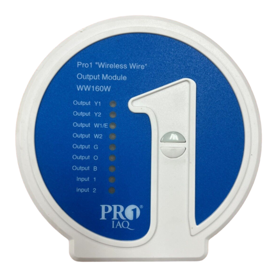
• WW160W Wireless Wire®
Applications Guide
Wireless Wire replaces 24V wiring. When the
input module is energized with 24V on any
terminal the paired terminal on the output
module closes. There are also terminals on
the output module that when energized with
24V will close the paired terminals on the
input module.
Input module up to:
7 terminal inputs / 2 terminal outputs
Output module up to:
7 terminal outputs / 2 terminal inputs
Table of Contents
Una versión española de este
manual puede ser descargada
en www.pro1iaq.com
® U.S. Registered Trademark. Patents pending.
Copyright © 2010 PRO1 IAQ, Inc. All rights reserved.
INSTALLATION MANUAL
Power Type
Hardwire (Common Wire)
Page
A trained, experienced technician
must install this product.
2
3-4
Carefully read these instructions. You
5
could damage this product or cause a
6 - 7
hazardous condition if you fail to follow
8
these instructions.
9
Need Help?
For assistance with this product please
visit http://www.pro1iaq.com or call Pro1
Customer Care toll-free at 888-Pro1iaq
(776-1427) during normal business hours
(Mon-Fri 9 AM - 6 PM Eastern)
1
Rev. 1012
Advertisement
Table of Contents

Related Manuals for Pro1 IAQ WW160W Wireless Wire


Summary of Contents for Pro1 IAQ WW160W Wireless Wire
-
Page 1: Table Of Contents
(776-1427) during normal business hours Una versión española de este (Mon-Fri 9 AM - 6 PM Eastern) manual puede ser descargada en www.pro1iaq.com ® U.S. Registered Trademark. Patents pending. Copyright © 2010 PRO1 IAQ, Inc. All rights reserved. Rev. 1012... -
Page 2: Wireless Modules Quick Reference
WIRELESS MODULES QUICK REFERENCE Getting to know the Wireless Wire ® Modules Important: Both wireless modules must have 24VAC power connected on R and C. These modules can only switch 24VAC power. Wireless signal is one way from Input Module to Output Module for all terminals except Input 1 and Input 2. -
Page 3: Installation Tips
INSTALLATION TIPS Wireless Modules - Basement Installation ATTIC INSTALLATION ON THE NEXT PAGE Wireless Range Range between the WW160W Input module and the WW160W Output module is up to 100 feet with no obstructions and up to 50 feet in standard residential construction. To extend the range try placing the modules closer together and/or further away from large metal objects. - Page 4 INSTALLATION TIPS Wireless Module - Attic Installation When performing an attic installation, instead of placing the wireless module in the attic, locate the closet nearest to the air conditioning unit. Then mount the wireless module high on the wall inside the closet or on the ceiling of the closet. This location will insure the wireless module is below the 120ºF maximum ambient temperature specification.
-
Page 5: Subbase Installation
SUBBASE INSTALLATION Mounting the wireless module subbase Wiring Note: Wire the wireless module’s subbase For vertical mount put one screw top the same way you would wire a and one screw bottom. hardwired thermostat subbase. For horizontal mount put one screw left and one screw right. -
Page 6: Wiring
WIRING Thermostat To Equipment Install the Input Module in a location that is convenient to wire the thermostat. Connect 24VAC to R and C on the input module. Install the output module in a location that is convenient to wire to the system control board. (this is the board that normally has the the themostat wire connected to) Connect 24VAC to the R and C on the output module. - Page 7 WIRING Air Handler to Multi Stage Compressor Install the Input Module in a location that is convenient to wire to the system control board. (this is the board that normally has the wire from the condensing unit connected to it.) Connect 24VAC to the R and C on the output module.
-
Page 8: Mounting The Wirless Modules
MOUNT THE WIRELESS MODULES Mount the Wireless Modules Note: Align the 4 tabs on the subbase with corresponding The wireless modules can be wired slots on the back of the wireless modules. from the back or the bottom. Then push gently until the thermostat or base module snaps in place. -
Page 9: Specifications & Contact Info
Operating ambient 90% non-condensing maximum Operating humidity 916 MHz Frequency 4.4”W x 4.4”H x .75”D Dimensions Pro1 IAQ Inc. 1111 S. Glenstone Suite 2-100 Spring eld, MO 65804 Toll-free: 1-888-Pro1iaq (776-1427) Toll Number (Outside the USA): 330-821-3600 Web: http://www.pro1iaq.com Hours of Operation: Monday - Friday 9 AM - 6 PM Eastern...
Need help?
Do you have a question about the WW160W Wireless Wire and is the answer not in the manual?
Questions and answers