Table of Contents
Advertisement
Quick Links
BEFORE YOU BEGIN
BEFORE YOU BEGIN
!
Read installation guide in illustration and word file carefully, and install the tank according to instructions in the guide to avoid
product damage and installation inconvenience caused by inappropriate operation.
!
All data contained is based upon the last product information available at the time of publication. Kohler Company reserves
the right to implement changes of product characteristics, packaging and availability at any time without further notice.
!
Do not apply erosive cleanser and solvent in the tank, which will damage tank spares and result in leakage in the tank.
Kohler will not be responsible for any damage related to above mentioned cleanser or solvent. Mild detergent can be used.
!
Do not apply spares that are not provided by Kohler, and please note that glass adhesive tape shall not be applied to the
installation of Kohler spares. Kohler will not be responsible for any damage related to installation with spares not provided by
Kohler.
!
This product complies with GB26730-2011.
!
!
!
!
!
GB26730-2011
Ordering Information
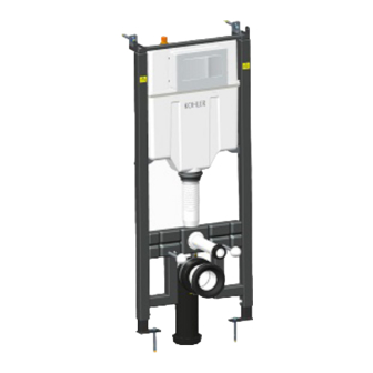
HYDRO-TOWER 300 In-Wall Tank(With Frame) ..................................................................................................................K-4178T
HYDRO-TOWER 300 3/4.5L In-Wall Tank With Frame.........................................................................................................K-4179T
HYDRO-TOWER 300 3/4.5L In-Wall Tank Without Frame ..................................................................................................K-10611T
DROPLET In-Wall Tank Faceplate (Not Supplied) ................................................................................................................K-4177T
BEVEL In-Wall Tank Faceplate (Not Supplied)......................................................................................................................K-8857T
PEBBLE In-Wall Tank Faceplate(Not Supplied) ..................................................................................................................K-20341T
LYNK Faceplate (Not Supplied)...........................................................................................................................................K-75890T
NOTE In-Wall Tank Faceplate(Not Supplied) ......................................................................................................................K-75891T
300
300 3/4.5
300 3/4.5
(
(
(
(
(
KOHLER CHINA INVESTMENT CO., LTD
1263048-T01-C
(
) ...............................................................................................................................K-4178T
.......................................................................................................................................K-4179T
..........................................................................................................................K-10611T
).........................................................................................................................................K-4177T
).........................................................................................................................................K-8857T
)..............................................................................................................................................K-20341T
) ..........................................................................................................................................K-75890T
) .................................................................................................................................................K-75891T
JING'AN DISTRICT, SHANGHAI, PRC
(
)
HYDRO-TOWER 300
K-4177T/K-8857T/K-20341T/K-75890T/K-75891T
NO.158, JIANG CHANG SAN ROAD,
POST CODE: 200436
158
©
Copyright Kohler China Investment Co., Ltd. 2017
-1-
©
INSTALLATION INSTRUCTIONS
IN-WALL TANK
K-4179T/K-4178T/K-10611T
200436
300
2017
Advertisement
Table of Contents

Related Manuals for Kohler HYDRO-TOWER 300


Summary of Contents for Kohler HYDRO-TOWER 300
- Page 1 Kohler will not be responsible for any damage related to above mentioned cleanser or solvent. Mild detergent can be used. Do not apply spares that are not provided by Kohler, and please note that glass adhesive tape shall not be applied to the installation of Kohler spares.
-
Page 2: Function Explanation
Function Explanation Anti flow-backwards Adjustment of inlet water level Adjustment of flushing volume Single/double gear flushing Assemble, disassemble and maintenance can be done without tools. Design And Installation Concept Of In-wall Tank Installation of in-wall tank is much easier and nice-looking comparative to that of traditional tank. Meanwhile, the space layout will be more reasonable due to the application of in-wall tank pipes and connectors. - Page 3 RECOMMENDES TOOLS AND MATERIALS RECOMMENDES TOOLS AND MATERIALS Open end/adjustable wrenches Allen wrench Knife File Hacksaw Masonry Level Screw driver Insulation tape Tape measure Seal tape Bushing Lubricant ROUGHING-IN Reference Value UNIT: mm K-4179T/K-4178T K-10611T 478 3 438 3 90~142 18~62 478 3 440 3...
- Page 4 Elbow Drain outlet 90mm, welding A B C 90mm Water Tank Bracket Discharge Elbow Drain outlet 110mm 110mm Water Tank Bracket Discharge Elbow Drain outlet 110mm, welding 110mm Kohler reserves the right to change marked dimensions without prior notice. 1263048-T01-C...
-
Page 5: Installation
INSTALLATION Way of Installation There are two ways to install this product: in-wall tank with frame & in-wall tank without frame In-wall Tank With Frame In-wall Tank Without Frame Installation For In-wall Tank With Frame Plug Paper Board Board A. Installation of In-wall Tank 1. - Page 6 3. Drill four holes with diameter of 10mm and depth of 80mm Bulge Screw with churn drilling as shown. A. Fill the bulge nail into the instruction hole on the wall, fix Mounting the fixing frame to the bulge nail, adjust the gasket and Bracket tighten the nut.
- Page 7 2. Tighten the long screw into the holes of the tank bracket Inlet Hole and cover the drainage hole with the big cap, cover the Tank Bracket inlet hole with the small cap. Small Cap Long Screw Drainage Hole Big Cap 3.
- Page 8 2. Tighten the long screw into the holes of the tank bracket Small Cap and cover the drainage hole with the big cap, cover the Inlet Hole inlet hole with the small cap. Long Screw Drainage Hole Big Cap Tank Bracket 3.
- Page 9 3. Install the big and small leak-proof gaskets on inlet pipe and outlet pipe ,then install it to corresponding pipes on the toilet tank. Small Leak-proof Gasket Inlet Pipe Drainage Pipe Big Leak-proof Gasket 4. 48mm-58mm of the long screw shall be reserved outside the wall as shown in the illustration.
-
Page 10: Faceplate Installation
E. Faceplate Installation Mask Slot B 1. Push slot A and slot B of the break water board forward and then insert into the detent. Break Water Board Tip 1: When installing the break water board, please make Slot A sure the slot is align with the detent. - Page 11 5. Install the faceplate as shown in the illustration. Put the lock on the faceplate directly on the reversed lock on supporting board, then push the faceplate and lock it. The installation shall begin from bottom to top. Faceplate Lock Supporting Faceplate Board...
- Page 12 2. Make sure of h according to dimensions of bowl and then Bulge Screw locate the installation hole of fixing bracket. Mark on the wall for appropriate position for fixing bracket, and drill four Fixing Bracket holes with diameter of 10mm and depth of 80mm with churn drilling as shown in illustration, and fill in the holes with bulge screw and tighten the screw to set the fixing bracket.
- Page 13 Mask 6. When finishing the brickwork, eliminate unwanted part of Sharp Knife the mask, the drainage pipe and the inlet pipe. Inlet Pipe Drainage Pipe 7. Fix faceplate according to step E and then it is ready for use. Full Flush Button Half Flush Button Finished Installation Illustration REMOVE AND MAINTENANCE OF THE OUTLET VALVE...
- Page 14 2. Loosen the long screws as shown. Supporting Board 3. Tighten the locknut to the marked position of OPEN to " " take out the supporting board. Locknut OPEN Supporting Board 4. Take out the supporting board as shown. Supporting Board 5.
- Page 15 7. Hold the top of the bracket, and unplug the locknut by pulling the bracket. Bracket 8. Turn on/off the water supply Turn on /off the water supply by turning the valve. Valve 9. Take out the bracket as shown. Bracket 10.
- Page 16 12. Hold the upside of the fixing lock, and take it out as shown. Fixing Lock Fixing Lock 13. Pull discharge valve along the arrow direction as shown to remove discharge valve. Outlet Valve 14. Remove discharge valve as shown and then take valve out for cleaning or adjusting.
-
Page 17: Troubleshooting Procedures
B. Adjust Drainage Valve Drainage volume and overflow level of the tank can be adjusted by drainage valve:1) heavy drainage adjustment: open adjustment switch to open the small hole. 2) slight drainage adjustment: adjust the height of floating box and Floating Box the water level of slight drainage will be at the bottom of the floating box. - Page 18 1263048-T01-C -18-...
Need help?
Do you have a question about the HYDRO-TOWER 300 and is the answer not in the manual?
Questions and answers