Table of Contents
Advertisement
Ultrasound Technologies Ltd
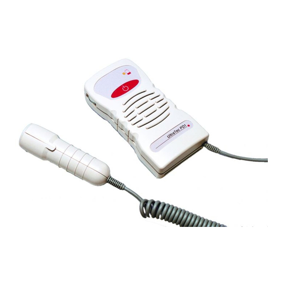
PD1 & Fetatrack 120 series Dopplers
Service manual
PD1 / FT120 service manual Issue 3 January 2007
©Ultrasound Technologies Ltd, Lodge Way, Portskewett, Caldicot, South Wales NP26 5PS, United Kingdom.
T +44 (0) 1291 425425
F: +44 (0) 1291 427093
E: ultratec@doppler.co.uk
W: www.doppler.co.uk
Advertisement
Table of Contents

Related Manuals for Ultrasound Technologies PD1 series

Summary of Contents for Ultrasound Technologies PD1 series
- Page 1 PD1 & Fetatrack 120 series Dopplers Service manual PD1 / FT120 service manual Issue 3 January 2007 ©Ultrasound Technologies Ltd, Lodge Way, Portskewett, Caldicot, South Wales NP26 5PS, United Kingdom. T +44 (0) 1291 425425 F: +44 (0) 1291 427093 E: ultratec@doppler.co.uk...
- Page 2 PD1combi fetal / vascular doppler PD1 / FT120 service manual Issue 3 January 2007 ©Ultrasound Technologies Ltd, Lodge Way, Portskewett, Caldicot, South Wales NP26 5PS, United Kingdom. T +44 (0) 1291 425425 F: +44 (0) 1291 427093 E: ultratec@doppler.co.uk...
- Page 3 Fetatrack series fetal dopplers Vascutrack series fetal dopplers PD1 / FT120 service manual Issue 3 January 2007 ©Ultrasound Technologies Ltd, Lodge Way, Portskewett, Caldicot, South Wales NP26 5PS, United Kingdom. T +44 (0) 1291 425425 F: +44 (0) 1291 427093 E: ultratec@doppler.co.uk...
-
Page 4: Table Of Contents
+ units General Assembly Drawings and Circuit Diagrams PD1 / FT120 service manual Issue 3 January 2007 ©Ultrasound Technologies Ltd, Lodge Way, Portskewett, Caldicot, South Wales NP26 5PS, United Kingdom. T +44 (0) 1291 425425 F: +44 (0) 1291 427093 E: ultratec@doppler.co.uk... -
Page 5: General Introduction
Retain the packing material for possible future use. Important Note: In the unlikely event that the instrument must be returned to Ultrasound Technologies for service or for any other reason, use the same packing material in which the instrument was delivered. -
Page 6: Re Order Information
Ultrasound Technologies Ltd Re - Order Information Listed below are the consumables used with the PD1 Series Pocket Dopplers: - Description Ultrasound Coupling Gel 0.25ltr. MN1604 series Alkaline Battery Symbols The following symbols have been used on the PD1 and are here defined according to IEC60601 IEC Symbol 878-02-02 Type B Equipment. -
Page 7: Guidelines For Identifying And Resolving Adverse Emc Conditions
If there is any doubt regarding the identification and resolution of adverse EM conditions, contact Ultrasound Technologies Ltd directly who will advise on the situation. The address can be found in the front of this manual. -
Page 8: Specification
Ultrasound Technologies Ltd Series specifications Ultrasound Frequency (PD1+ / PD1dwr / fetatrack 120+) 2 MHz continuous wave fixed probe (PD1v / PD1cv / Vascutrack 120) 5 or 8 MHz continuous wave fixed probe (PD1 combi /PD1+ combi / Combitrack) 2, 3, 5 or 8MHz interchangeable probe Transducer 2 crystal narrow beam. -
Page 9: Description Of The Instrument
Ultrasound Technologies Ltd Description of the Instrument 2.1. Audio Unit PD1 (Fetatrack 120, Babypulse) The following functions are found in the relevant page of the operating instructions. UNIT ON/OFF On / Off control. BATTERY LOW LED indicator to show when the battery has reached a point when it requires changing. - Page 10 Ultrasound Technologies Ltd 2.2. Audio Unit PD1+ (PD1dwr / fetatrack 120+ / babypulse +) The following functions are found in the relevant page of the operating instructions. UNIT ON/OFF On / Off control. VOLUME CONTROL Rotary edge potentiometer, which increases or decreases the setting of the volume.
- Page 11 Ultrasound Technologies Ltd 2.3. Audio Unit PD1v The following functions are found in the relevant page of the operating instructions. UNIT ON/OFF On / Off control. BATTERY LOW LED indicator to show when the battery has reached a point when it requires changing.
-
Page 12: Audio Unit
Ultrasound Technologies Ltd 2.4. Dismantling Instructions Special Note: -The instrument must not be dismantled when in use on a patient, ensure all accessories are disconnected. 2.5. Audio Unit The Audio unit houses the main circuit board. To remove the circuit board, turn the unit onto it's front and remove the three M4 countersunk screws. - Page 13 Ultrasound Technologies Ltd The transducers, loudspeaker and battery connections are ‘hard wired’ to the PCB. De-solder the connections at J4 (retractile cable) and J3 (loudspeaker), the PCB can then be pulled clear of the case. ©Ultrasound Technologies Ltd Page 9 of 32...
-
Page 14: Transducers
Ultrasound Technologies Ltd 2.6 Transducers The transducers are a ‘sealed unit’. However, it is possible to gain access to the 2 MHz assembly by removing the two blanking grommets and M3 countersink screws. Removing the screws will allow the assembly to be split along its length. Gently prise the assembly apart. -
Page 15: Circuit Description
Ultrasound Technologies Ltd Circuit Description Introduction The circuit has been divided into functional blocks with each block being described separately, the blocks are as follows: • Audio Unit Power Supply • Battery Low Indicator • Ultrasound Transducer • Oscillator and Detector •... -
Page 16: Velocity Processor
Ultrasound Technologies Ltd With the exception of the 2MHz Fetal transducer, the electronics are housed in the main audio unit. The oscillator and detector are built up of four discrete sections. These are the master oscillator, transmitter amplifier, receiver amplifier and detector. -
Page 17: Test And Calibration
Ultrasound Technologies Ltd Test and Calibration Introduction The following sections detail tests to ensure that the unit is operating within specification. These tests may be performed in whole or part, however, if any repairs are carried out to the power supply circuits then it is recommended that the whole test / calibration procedure is undertaken. -
Page 18: Transducer
Ultrasound Technologies Ltd Using a pair of tweezers, Introduce noise into pin 4 of J4. Rotate the volume control through its complete range of travel and observe the audio output from the speaker increases and decreases accordingly. Transducer Transmitter Set the DC Power Supply to 9Vdc, solder the +ve lead to pin 1 of J1 and the –ve lead to J1 pin 2 on the board under test. -
Page 19: Fault Finding Guidelines
Ultrasound Technologies Ltd Fault finding guidelines This section is an aid to trouble shooting and should be used in conjunction with the relevant circuit diagrams found at the rear of this manual. In each case the re calibration must be carried out after any repair. -
Page 20: Parts Lists
Ultrasound Technologies Ltd Parts list The following section contains parts lists for the following items: - • PD1+ Audio PCB assembly • PD1 Audio PCB assembly • PD1 2MHz Probe assembly • PD1 Final assembly • PD1+ Final assembly PD1+ Audio PCB Assembly... - Page 21 Ultrasound Technologies Ltd IC Digital ICM7211AMIM44 Harris Diode 10BQ040 Diode BAS16 D2,5 Crystal 12MHz 86SMX Transistor RFD8P05SM Harris Resistors 1% 0805 Samsung/Phillips/ROHM R5,6 Resistors 1% 0805 100R Samsung/Phillips/ROHM Resistors 1% 0805 Samsung/Phillips/ROHM Resistors 1% 0805 Samsung/Phillips/ROHM Resistors 1% 0805 Samsung/Phillips/ROHM...
- Page 22 Ultrasound Technologies Ltd PD1 Audio PCB Assembly Device Value Device Type Circuit Reference Quantity Capacitor 470uF Electrolytic Axial 10V Panasonic SU ECEB1AU471 Capacitor 100uF Min Electrolytic 16V Nippon Chemi-con SRA / C1,8,9,11,12 Samsung SSM Capacitor 10uF tant 20V AVX / Kemet case size A...
- Page 23 Ultrasound Technologies Ltd PD1 2MHz Transducer Assembly Value Description Device Type Circuit Reference Quantity Capacitor 100uF Min Electrolytic 16V Nippon Chemi-con SRA / C5,8,12 Samsung SSM Capacitor 1u0F tant 35V case size A C4,11 Capacitor 100nF Mono Ceramic 0805 series Z5U dielectric...
- Page 24 Ultrasound Technologies Ltd Faceplate PD1D102 Probe Cover PD1D101 M3 x16 Pozi C'sk screw M3 Full nut Cover plug ©Ultrasound Technologies Ltd Page 20 of 32 PD1 / FT120 service manual Issue 3 January 2007...
- Page 25 Ultrasound Technologies Ltd PD1 Audio Unit General Assembly Description Part Number Quantity Case Front PD1D105 Case Rear PD1D106 Battery Slide PD1D104 Loudspeaker Retractile cable PD1D100 Label front PD1D108 Label rear PD1D108 Front Membrane PD1D108 M3 x 6 Pozi Pan screw...
- Page 26 Ultrasound Technologies Ltd PD1+ General Assembly Description Part Number Quantity Case Front PD1D105 Case Rear PD1D106 Battery Slide PD1D104 Loudspeaker Retractile cable PD1D100 Label front PD1+ PD1D108 Label rear PD1D108 Front Membrane PD1+ PD1D108 M3 x 6 Pozi Pan screw...
- Page 27 Ultrasound Technologies Ltd Circuit Diagrams & Engineering Drawings The following section contains circuit diagrams and Engineering Drawings: - ©Ultrasound Technologies Ltd Page 23 of 32 PD1 / FT120 service manual Issue 3 January 2007...
- Page 28 Ultrasound Technologies Ltd • PD1 Audio PCB Layout ©Ultrasound Technologies Ltd Page 24 of 32 PD1 / FT120 service manual Issue 3 January 2007...
- Page 29 Ultrasound Technologies Ltd PD1+ Audio PCB Layout ©Ultrasound Technologies Ltd Page 25 of 32 PD1 / FT120 service manual Issue 3 January 2007...
- Page 30 Ultrasound Technologies Ltd Ultrasound Technologies Ltd PD1 Probe PCB Layout ©Ultrasound Technologies Ltd, Lodge Way, Portskewett, Caldicot, South Wales NP26 5PS, United Kingdom. ©Ultrasound Technologies Ltd, Lodge Way, Portskewett, Caldicot, South Wales NP26 5PS, United Kingdom. T +44 (0) 1291 425425...
- Page 31 Ultrasound Technologies Ltd PD1 General Assembly ©Ultrasound Technologies Ltd, Lodge Way, Portskewett, Caldicot, South Wales NP26 5PS, United Kingdom. T +44 (0) 1291 425425 F: +44 (0) 1291 427093 E: ultratec@doppler.co.uk W: www.doppler.co.uk...
- Page 32 Ultrasound Technologies Ltd PD1+ GA ©Ultrasound Technologies Ltd, Lodge Way, Portskewett, Caldicot, South Wales NP26 5PS, United Kingdom. T +44 (0) 1291 425425 F: +44 (0) 1291 427093 E: ultratec@doppler.co.uk W: www.doppler.co.uk...
-
Page 33: 2Mhz Transducer Assembly
Ultrasound Technologies Ltd 2MHz Transducer Assembly ©Ultrasound Technologies Ltd, Lodge Way, Portskewett, Caldicot, South Wales NP26 5PS, United Kingdom. T +44 (0) 1291 425425 F: +44 (0) 1291 427093 E: ultratec@doppler.co.uk W: www.doppler.co.uk... - Page 45 Ultrasound Technologies Service Engineer Guide To be used for work carried out on: Document contains information of signals at key points throughout the specified product. The following images are oscilloscope snap shots of signals acquired from the PD1 Audio and Power control board.
- Page 46 Q2 DRAIN Q2 GATE U3 PIN 1 U3 PIN 3 U1 PIN 1 U1 PIN 1 UNIT SWITCHED OFF UNIT SWITCHED ON...
- Page 47 U1 PIN 2, UNIT SWITCHED ON U1 PIN 2 OFF, UNIT SWITCHED OFF U1 PIN 3 UNIT SWITCHED ON U1 PIN 3 UNIT SWITCHEDOFF U1 PIN 4 & 6 = GND...
- Page 48 U1 PIN 5 UNIT SWITCHED ON U1 PIN 5 UNIT SWITCHED OFF U1 PIN 7 & 8 = GND U1 PIN 9 UNIT SWITCHED ON U1 PIN 9 UNIT SWITCHED OFF...
- Page 49 U1 PIN 10 UNIT SWITCHED ON U1 PIN 10 UNIT SWITCHED OFF U1 PIN 11 UNIT SWITCHED ON U1 PIN 11 UNIT SWITCHED OFF U1 PIN 12 UNIT SWITCHED ON U1 PIN 12 UNIT SWITCHED OFF...
- Page 50 U1 PIN 13 = FLOATING U1 PIN 14 UNIT SWITCHED ON U1 PIN 14 UNIT SWITCHED OFF U2 PINS 2 & 4 = GND U2 PIN 1STROKING FACEPLATE...
- Page 51 U2 PIN 3 STROKING FACEPLATE U2 PIN 5 STROKING FACEPLATE U2 PIN 6 SUPPLY U2 PIN 7 U2 PIN 8 STROKING FACEPLATE...
- Page 52 SK1 PINS 2, 3 & 4 STROKING FACEPLATE PIN 1 = GND J4 PIN 1 SUPPLY TO TRANSDUCER J4 PIN 4 STROKING FACEPLATE SIGNAL FROM TRANSDUCER THE FOLLOWING IMAGES ARE SIGNALS TAKEN FROM THE POCKET DOPPLER FETAL TRANSDUCER 2MHZ. Q1 COLLECTOR Q1 BASE...
- Page 53 Q1 EMITTER, TRANSMITTER CIRCUIT, Q2 SOURCE TRANSMITTER CIRCUIT TRANSMITTER CIRCUIT Q2 DRAIN Q3 COLLECTOR ( Q2 GATE = GND ) TRANSMITTER CIRCUIT TRANSMITTER CIRCUIT Q3 BASE L2 PIN 1...
- Page 54 TRANSMITTER CIRCUIT TRANSMITTER CIRCUIT L2 PIN 3 TRANITTED SIGNAL L2 PIN 4 RECEIVER CIRCUIT RECEIVER CIRCUIT Q5 GATE Q5 DRAIN RECEIVER CIRCUIT RECEIVER CIRCUIT Q4 GATE Q4 DRAIN...
- Page 55 RECEIVER CIRCUIT RECEIVER CIRCUIT Q6 DRAIN Q6 GATE RECEIVER CIRCUIT TRANSDUCER RECEIVER CIRCUIT Q6 SOURCE U1 PIN 1 TRANSDUCER RECEIVER CIRCUIT TRANSDUCER RECEIVER CIRCUIT U1 PIN 2 U1 PIN 3...
- Page 56 TRANSDUCER RECEIVER CIRCUIT TRANSDUCER RECEIVER CIRCUIT U1 PIN 5 U1 PIN 6 TRANSDUCER RECIEVER CIRCUIT TRANSDUCER RECEIVER OUTPUT TO AUDIO U1 PIN 7 BOARD J1 PIN 4...
- Page 75 Ultrasound Technologies Ltd Lodge Way Portskewett Caldicot NP26 5PS United Kingdom Tel: 01291 425425 Fax: 01291 427093 Email: ultratec@doppler.co.uk Web: www.doppler.co.uk...
Need help?
Do you have a question about the PD1 series and is the answer not in the manual?
Questions and answers