
Subscribe to Our Youtube Channel
Related Manuals for PAT DS 350 / 1319 Graphic


Summary of Contents for PAT DS 350 / 1319 Graphic
- Page 1 PAT America, Inc. www.patamerica.com LOAD MOMENT INDICATOR DS 350 / 1319 Graphic OPERATOR’S MANUAL P/N 050-350-191-319 REV 8, 05/19/2003 © PAT Rev. 8 05/19/03 191319_8.DOC...
- Page 2 DS 350 / 1319 NOTICE PAT America, Inc. makes no warranty of any kind with regard to this material, including, but not limited to, the implied warranties of merchantability and/or its fitness for a particular purpose. PAT America, Inc. will not be liable for errors contained in this manual or for incidental or consequential damages in connection with the furnishing, performance, or use of this manual.
-
Page 4: Table Of Contents
9.1 G ENERAL ....................38 9.2 M ALFUNCTION ABLE ....................39 9.3 O PERATING RRORS APPENDIX A: DETAILED SYMBOL EXPLANATION OF BOOM EXTENSIONS ....41 APPENDIX B: DETAILED SYMBOL EXPLANATION OF COUNTERWEIGHT OPTIONS ..42 © PAT Rev. 8 05/19/03 191319_8.DOC... -
Page 6: General Information
General Information 1 GENERAL INFORMATION The PAT Load Moment Indicator (LMI) DS 350 has been designed to provide the crane operator with the essential information required to operate the machine within its design parameters. Using different sensing devices, the Load Moment Indicator monitors various crane functions and provides the operator with a continuous reading of the crane’s capacity. -
Page 7: System Description
DS 350 / 1319 3 SYSTEM DESCRIPTION The PAT Load Moment Indicator DS 350 consists of a central micro processor unit, operating console, length/angle sensor, pressure transducers, and anti-two block switches. The system operates on the principle of reference/real comparison. The real value, resulting from the pressure measurement is compared with the reference data, stored in the central processor memory and evaluated in the micro processor. - Page 8 General Information Fig. 1: Components of the LMI system PAT DS 350 1 Anti Two-Block switches 2 Pressure Transducers 3 Length/Angle sensor 4 Operating console 5 Central-Micro-Processor unit © PAT Rev. 8 05/19/03 191319_8.DOC...
-
Page 9: System Function
Next is the interactive input of the reeving. Now the LC display shows in symbols all inputs and awaits acknowledgment or cancelling. Upon acknowledgment of the inputs the system is ready for operation. © PAT Rev. 8 05/19/03 191319_8.DOC... -
Page 10: Operating Console
Button and Control Light “TARE” F1 Button "Function 1" Button and Control Light “LIMITS” F2 Button "Function 2" Button and Control Light “SELECT F3 Button "Function 3" OPERATING MODE” F4 Button "Function 4" © PAT Rev. 8 05/19/03 191319_8.DOC... - Page 11 Operator's Manual DS 350 / 1319 Fig. 2: Operating Console © PAT Rev. 8 05/19/03 191319_8.DOC...
- Page 12 A2B / LMI system is deactivated. Button and Control Light “Alarm Stop” This ALARM STOP BUTTON (6) allows the audible alarm to be silenced for approximately 15 seconds by pressing this button. Reference ⇒ “Audible Alarm” (12). © PAT Rev. 8 05/19/03 191319_8.DOC...
- Page 13 Button "INFO" Button to start the function "information crane configuration" Please refer to ⇒ Chapter 5.2. Button "CONTROL" Button to start additional functions. Please refer to ⇒ Chapter 5.3. © PAT Rev. 8 05/19/03 191319_8.DOC...
- Page 14 • Never use the by-pass function to either overload or operate the crane in a non-permissible range. © PAT Rev. 8 05/19/03 191319_8.DOC...
- Page 15 This button can be operated only if key switch (13) is turned to position B. After pushing this button, the control lever lockout function of the LMI is deactivated. The Override Key Warning Light (5) flashes to indicate that the cut-off function is deactivated. © PAT Rev. 8 05/19/03 191319_8.DOC...
-
Page 16: Configuration Setup
The correct setting is of utmost importance for the proper functioning of the system and the crane. Therefore, only operators who are thoroughly familiar with the crane and the operation of the system should execute the setting of the system according the operating configuration of the crane. © PAT Rev. 8 05/19/03 191319_8.DOC... - Page 17 Select Next Numeral Confirm Selected Operating Code • Setting the boom configuration Main Boom / Aux. Boom Nose Operation Operation With Boom Extensions Rigging Mode Operation* For Cranes With Rigging Mode Outrigger Box Installation Only © PAT Rev. 8 05/19/03 191319_8.DOC...
- Page 18 Appendix B in this manual for detailed symbol explanation of counterweight. • Setting The Hoist Configuration Front Hoist Rear Hoist • Setting The Outrigger Configuration On Rubber Outrigger Position 0% Outrigger Position 50% Outrigger Position 100% © PAT Rev. 8 05/19/03 191319_8.DOC...
- Page 19 At the end of the procedure all inputs are represented once again in symbolic forms. If inputs have been made, the corresponding symbols are filled in black. Quick Setting The Reeving Cancel Procedure (⇒ Chapter 4.3) Confirm Inputs Quick Hoist Line Selection (⇒ Chapter 4.2) © PAT Rev. 8 05/19/03 191319_8.DOC...
-
Page 20: Quick Setting Of The Reeving
(Select Again The Function Upon Faulty Input) Note: If a configuration is selected which is not available on the present crane, the system will not accept the selection and the display will indicate the error code E04. © PAT Rev. 8 05/19/03 191319_8.DOC... -
Page 21: Quick Hoist Line Selection
Note: If a configuration is selected which is not available on the crane, the system will not accept the selection and the display will indicate the error code E04 © PAT Rev. 8 05/19/03 191319_8.DOC... -
Page 22: Operation
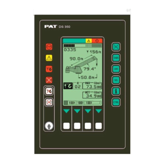
LMI screen (example for value representation). utilization bargraph tip height operation code number boom length boom angle radius reeving max. load (parts of line) actual load only for cranes with boom control system © PAT Rev. 8 05/19/03 191319_8.DOC... - Page 23 (⇒ see Chapter 5.1.3) Symbol radius limitation: continuously visible radius limitation active blinking: range limits exceeded (⇒ see Chapter 5.1.4) E#### Error code No. #### (⇒ see Chapter 8 "Troubleshooting") © PAT Rev. 8 05/19/03 191319_8.DOC...
-
Page 24: Limit Setting
Depending on the crane type, not all functions listed below are available. Overview limits: Slewing Angle Limitation / Work Area Definition (⇒ Chapter 5.1.1) Tip Height Limitation (⇒ Chapter 5.1.2) Boom Angle Limitation (⇒ Chapter 5.1.3) Radius Limitation (⇒ Chapter 5.1.4) © PAT Rev. 8 05/19/03 191319_8.DOC... -
Page 25: Slewing Angle Limitation / Work Area Definition
• set / delete left slewing angle: Select limit: Select left limit set: delete: Position boom to delete left required left limit angle limit value. program present slewing angle as left limit quit function © PAT Rev. 8 05/19/03 191319_8.DOC... - Page 26 Display shows symbols and angle values of the programmed slewing angle limit Display shows symbols without angle values Quit function © PAT Rev. 8 05/19/03 191319_8.DOC...
- Page 27 Move the boom tip to one end of the virtual wall you want to set. Sets a point in the working area to start a wall Exits the screen © PAT Rev. 8 05/19/03 191319_8.DOC...
- Page 28 Move the boom tip to the other end of the additional virtual wall you want to set. Sets the third point to create a second wall Exits the screen and deletes all virtual wall settings © PAT Rev. 8 05/19/03 191319_8.DOC...
- Page 29 DS 350 / 1319 Upon pressing SET, the second wall is created. Accepts the defined walls and exits Allows for further walls to be added Exits the screen and deletes all virtual wall settings © PAT Rev. 8 05/19/03 191319_8.DOC...
-
Page 30: Tip Height Limitation
Move the tip to delete tip the required height limitation upper limit. present tip height as upper limit Display shows symbol and value of the programmed height limit Display shows symbol without values Quit function © PAT Rev. 8 05/19/03 191319_8.DOC... -
Page 31: Boom Angle Limitation
Display shows symbol with value of the upper angle limit Display shows symbol without value of the upper angle limit Quit function • Set / delete lower limit angle © PAT Rev. 8 05/19/03 191319_8.DOC... - Page 32 Display shows symbol with lower angle limit Display shows symbol without value of lower limit angle Quit function © PAT Rev. 8 05/19/03 191319_8.DOC...
-
Page 33: Radius Limitation
Quit function © PAT Rev. 8 05/19/03 191319_8.DOC... - Page 34 Display shows symbol with radius value of max. limit Display shows symbol without value of max. radius Quit function © PAT Rev. 8 05/19/03 191319_8.DOC...
-
Page 35: Info Crane Configuration
Press key "INFO". The display shows the crane symbol representing the adjusted configuration (marked black), the extended operating code number and the reeving number (parts of line). • End Function Press again key "INFO". © PAT Rev. 8 05/19/03 191319_8.DOC... -
Page 36: Display Contrast Control
During normal LMI operation the display contrast can be adjusted also by pressing one of the following buttons: F2 (brighten display) or F3 (darken display). brighten darken © PAT Rev. 8 05/19/03 191319_8.DOC... -
Page 37: Pre-Operation Inspection And Calibration Verification
In that case the anti two-block switch has to be locked with the red Anti Two-Block Retainer, which is fixed with a red lanyard (not shown) at the anti two-block switch. © PAT Rev. 8 05/19/03 191319_8.DOC... -
Page 38: Installation Of Anti Two-Block Retainer In Locking Position
3. For storage slide the retainer from right side (5) over the Anti Two-Block switch until the clips (A) lock into the holes (B). Fig. 3: Removal of the Anti Two- Fig. 4: Retainer in Storage Position Block Retainer © PAT Rev. 8 05/19/03 191319_8.DOC... -
Page 39: Pre-Operation Inspection And Calibration Verification
(17) should sound, the anti two-block alarm light (24) should light and the boom telescope out function should be stopped. Lower the load handling device slightly to eliminate this condition. © PAT Rev. 8 05/19/03 191319_8.DOC... - Page 40 3. Check that the display of the main boom angle agrees with the actual boom angles. 4. Check that the display of the operating radius of the crane agrees with the actual radius. 5. Check the load display by lifting a load of known weight © PAT Rev. 8 05/19/03 191319_8.DOC...
-
Page 41: Operation
If any of the displays reflects a deviation between displayed and actual values, an authorized PAT service representative shall be called for repair of the system or reverification of the crane’s LMI calibration. -
Page 42: Service And Maintenance
5. Check the pressure transducers at the hoist cylinder(s) and the connecting hoses for oil leakage. Other than correcting the problems identified in the Malfunctions Table and replacing faulty mechanical parts and cables, no other repairs shall be performed by non expert personnel. © PAT Rev. 8 05/19/03 191319_8.DOC... -
Page 43: Troubleshooting
Center Mid not fully extended flashing % Telescope out of permissible sequence NOTE: If there is any Error Code displayed on the console which is not listed in the Malfunctions Table you shall call the Local Distributor. © PAT Rev. 8 05/19/03 191319_8.DOC... -
Page 44: Operating Errors
Length sensor adjustment For elimination refer to service manual. changed i.e. length sensor cable slid off the length sensor drum. © PAT Rev. 8 05/19/03 191319_8.DOC... - Page 45 Move boom to permitted area Boom is about to collide with the engine hood, switch off Approaching prohibited area Move boom to permitted area Boom is about to collide with the engine hood, prewarning © PAT Rev. 8 05/19/03 191319_8.DOC...
-
Page 46: Appendix A: Detailed Symbol Explanation Of Boom Extensions
Swingaway/ swingaway bifold with fly with fly/tele stowed main boom Swingaway/ swingaway/ bifold without bifold without fly stowed on main boom bifold with fly fly stowed on stowed on main boom main boom © PAT Rev. 8 05/19/03 191319_8.DOC... -
Page 47: Appendix B: Detailed Symbol Explanation Of Counterweight Options
A with counterweight B with counterweight A + B only for cranes with auxiliary counterweight: without auxiliary counterweight with auxiliary counterweight © PAT Rev. 8 05/19/03 191319_8.DOC... - Page 48 O.K. button to confirm and to proceed with console programming © PAT Rev. 8 05/19/03 191319_8.DOC...
Need help?
Do you have a question about the DS 350 / 1319 Graphic and is the answer not in the manual?
Questions and answers