
Subscribe to Our Youtube Channel
Related Manuals for evodesk PRO

Summary of Contents for evodesk PRO
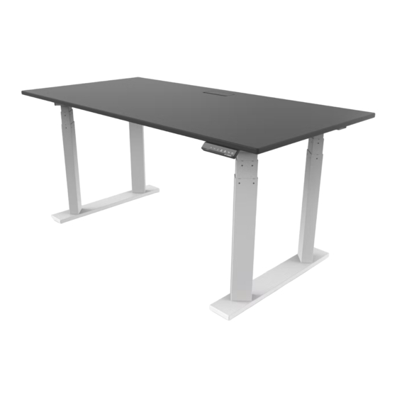
- Page 1 P O W E R A D J U S T A B L E D E S K ASSEMBLY & OPERATION MANUAL 90.014.01.0280v.A ED51115-SM...
-
Page 2: Table Of Contents
We appreciate the trust and confidence you have placed in our company. We are committed to providing you the best possible value in power adjustable desks. We are sure that your Evodesk will provide you many years of enjoyment and health. -
Page 3: Caution, Use & Liability
CAUTION Make sure no obstacles are in the desk’s WARNING! PINCH POINT path. Make sure the desktop is not Keep hands and fingers clear touching any walls. Make sure all cords are appropriate length to accommodate the change in height. Keep children away from electric height-adjustable desks, control units and handsets. -
Page 4: Parts & Components
PARTS & COMPONENTS TOOLS REQUIRED 4mm Allen Wrench (included) Phillips Head Screwdriver Tape Measure COMPONENTS INCLUDED Columns Feet Upper Frame Center Rails Upper Brackets Control Box Controller(s) Power Cord Lift Cables Leveling Studs (51”) Link Cable HARDWARE INCLUDED Machine Screws Machine Screws Wood Screws Cable Clips... -
Page 5: Table Of Contents
Control Box B Controller Power Cord Lift Cables Leveling Studs (pre-installed) Machine Screws: M6x14 Machine Screws: M6x10 Phillips Screws:10-24 x ½” (Shipped separately in box with Evodesk desktop if purchased) Wood Screws: ST M5x16 Cable Clips Link Cable Components Diagram - 3... -
Page 6: Assembly Instructions
ASSEMBLY INSTRUCTIONS BEFORE YOU BEGIN Lay out all components and hardware to ensure that you have all the parts listed on the parts page. STEP 1 Lay the frame with the Rubber Pads facing down. Insert a column into one of the openings as shown. STEP 2 Use four of the M6-10mm screws to secure the Columns to the Upper Frame. - Page 7 ASSEMBLY INSTRUCTIONS cont. STEP 3 Repeat for the other opening on the Upper Frame. STEP 4 Attach one of the feet to the ends of the Columns using eight of the M6-14mm screws. Assembly Instructions cont. - 5...
- Page 8 ASSEMBLY INSTRUCTIONS cont. STEP 5 Repeat Steps 1 through 6 to complete the second column group. STEP 6 Align the hole furthest from the columns with the steel insert on the desktop. Attach with one of the 10-24 screws included with the desktop.
- Page 9 ASSEMBLY INSTRUCTIONS cont. STEP 7 Align the Upper Bracket with the Upper Frame as shown. Use three 10-24 screws included with the desktop. These should also only be screwed in 75% of the way. Assembly Instructions cont. - 7...
- Page 10 ASSEMBLY INSTRUCTIONS cont. STEP 8 Secure the Upper Bracket to the Upper Frame using four of the M6-10 screws. Firmly tighten after all four have been started. STEP 9 Slide in both Center Rails into the openings of the Upper Frame as shown. Assembly Instructions cont.
- Page 11 ASSEMBLY INSTRUCTIONS cont. STEP 10 Slide the second column group over the exposed ends of the Center Rails. STEP 11 Adjust the second column group position to align the outermost frame hole with matching insert on the desktop. Attach with one of the 10-24 screws again being only about 75% inserted.
- Page 12 ASSEMBLY INSTRUCTIONS cont. STEP 12 Align the second Upper Bracket with the second Upper Frame as shown. Use the remaining three 10-24 screws included with the desktop. STEP 13 Secure the Upper Bracket to the Upper Frame using four of the M6-10 screws.
- Page 13 ASSEMBLY INSTRUCTIONS cont. STEP 14 Now all the 10-24 screws can be firmed tightened. STEP 15 Use the eight M6-10mm screws in the locations shown to lock the Center Rails. These screws should be firmly tightened. Tight- ening can also be applied to the looser screws from Step 2. (3 screws from each column should be accessible.) Assembly Instructions cont.
- Page 14 ASSEMBLY INSTRUCTIONS cont. STEP 16 Use the two wood screws to attach the Control Panel in either the right or left hand position. Do not over-tighten these screws, only firm enough to prevent the panel from moving. Right Hand Position Left Hand Position STEP 17 The Control Box attached by placing it between the frame and sliding...
- Page 15 ASSEMBLY INSTRUCTIONS cont. STEP 18 Connect the Columns to the Control Box nearest to them. Use the Link cable to connect to connect the two Control Boxes. The Power Cable should have two connectors that should each connect to a Control Box.
- Page 16 ASSEMBLY INSTRUCTIONS cont. STEP 20 With two people, firmly grab the desk and slowly turn it right-side-up. STEP 21 Plug the Power Cord into a 110v outlet. Reset Procedure: Press and hold DOWN button on Controller (#7) until desk reaches its lowest height. Release DOWN button. Press and hold DOWN button again until LED displays “RST”...
-
Page 17: Troubleshooting
“E01 - E13”, confirm that all wired connections are secure (legs to cables, cables to control box). Then perform the reset procedure outlined in Step 21. If the error message persists after the reset procedure, contact EvoDesk. If the height difference between the legs exceeds 1.5 inches, stop the reset procedure and contact EvoDesk immediately. -
Page 18: Warranty
Products, you agree to be bound by and accept these terms and conditions. The Evodesk Product is warranted by Manufacturer to be free from defects in material and workmanship for five (5) years from the date of purchase. - Page 19 FROM A COURSE OF DEALING, USAGE OR TRADE PRACTICE. Limitation of Liability IN NO EVENT WILL EVODESK OR ITS AFFILIATES OR SUPPLIERS BE LIABLE FOR ANY LOSS OF USE, INTERRUPTION OF BUSINESS, LOST PROFITS, OR LOST DATA, OR INDIRECT, SPECIAL, INCIDENTAL OR CONSEQUENTIAL DAMAGES OF ANY KIND...
- Page 20 Your lifestyle and career evolves. We made Evodesk to evolve with you. This means Evodesk may be the last desk you’ll ever need to buy. The Evolution frame system moves between 48”, 60” and 72” or larger without having to buy a new desk.
- Page 21 NOTES...
- Page 22 NOTES...
- Page 24 2251 Picadilly Drive Suite. C-341 Austin, TX 78660 (888) 615-5721 evodesk.com For technical support visit evodesk.com/support...
Need help?
Do you have a question about the PRO and is the answer not in the manual?
Questions and answers