Advertisement
DESCRIPTION
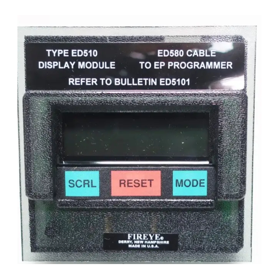
The ED510 Display Module is designed to operate with the FLAME-MONITOR Burner Manage-
ment Control System using the EP and EPD style (remote mount only for EPD style) programmer
modules as well as the MicroM series of controls. The ED510 display module provides the following
features and capabilities:
•
Two (2) line by sixteen (16) character backlit LCD display.
•
Continuous display of current burner operating status, including first out annunciation in the
event of a lockout condition.
•
Three (3) key, tactile dome keypad to provide historical information of the burner, last six (6)
lockout conditions (with burner cycle and burner hour time stamp), assign messages associated
with the operation of the E300 expansion module, and diagnostic messages.
•
Design mounts directly onto the front face of the EP style programmers.
•
RJ style connector for connection to the EP and EPD programmer.
•
Remote display capability with the EP and EPD style programmers and MicroM system using
standard DIN sized opening and remote mounting kit. Refer to Bulletin E-8002.
•
Weather proof housing (NEMA 4 using remote mounting kit 129-145-1, -2).
INSTALLATION
The ED510 display mounts directly onto the front of the EP style programmers. The ED510 can be
mounted onto the programmer when the programmer is either installed in the EB700 chassis or not.
•
Remove power from the EB700 chassis if the programmer is installed in the chassis.
•
Slide the bottom of the ED510 chassis onto the two (2) mounting tabs on the face of the EP style
programmer.
•
Tilt the ED510 display towards the cover until the mounting tab on top of the ED510 display
snaps into position into the opening on the face of the EP programmer.
•
Install the ED580 cable (provided) into the RJ style connectors on both the ED510 display and
EP style programmers.
— Insert the EP style programmer and ED510 display into the second slot on the EB700 chassis
For information on how to mount the ED510 display remotely for the EP, EPD style programmers
and MicroM systems, refer to Bulletin E-8002.
(marked "Programmer Module") and restore power.
ED510 DISPLAY MODULE
FIREYE
MANAGEMENT CONTROLS
®
APRIL 3, 2013
FOR USE WITH
®
FLAME-MONITOR™
AND MicroM™ BURNER
APPROVED
ED-5101
1
Advertisement
Table of Contents

Related Manuals for Fireye ED510


Summary of Contents for Fireye ED510
- Page 1 • Remove power from the EB700 chassis if the programmer is installed in the chassis. • Slide the bottom of the ED510 chassis onto the two (2) mounting tabs on the face of the EP style programmer. • Tilt the ED510 display towards the cover until the mounting tab on top of the ED510 display snaps into position into the opening on the face of the EP programmer.
-
Page 2: Ordering Information
32 F — 140F (0 C— 60C) BACKLIT LCD DISPLAY The ED510 display has a two (2) line by sixteen (16) character backlit LCD display. The backlit function is continuously energized. Contrast Control: The contrast for the LCD display is factory set. If the contrast must be adjusted for any reason (e.g.: remote mounting), a potentiometer is provided on the back of the ED510 display... -
Page 3: General Operation
® GENERAL OPERATION The ED510 displays current burner status, first out annunciation in the event of a lockout condition, historical burner information, detailed lockout information of the last six (6) lockout conditions, diagnostic messages, and the ability to program messages associated with the E300 Expansion Mod- ule. - Page 4 Pilot flame proven during PTFI. Flame signal strength displayed in upper right PTFI hand corner. FLAME SIGNAL MTFI Main flame proven during MTFI. Flame signal strength displayed in upper right FLAME SIGNAL hand corner. Modulator motor sent to auto position (term 10-11 made). Flame signal strength AUTO displayed in upper right hand corner.
- Page 5 ® The control has held for more than 10 minutes waiting for the low fire switch LOCKOUT PURGE (M-D) to close. M-D LIMIT OPEN The running interlock circuit (3-P) has opened during the pilot trial for ignition LOCKOUT PTFI period. Applies to non-recycle programmers only. 3-P INTLK OPEN The running interlock circuit (3-P) has opened during the main trial for ignition LOCKOUT MTFI...
-
Page 6: Diagnostic Messages
The "Run-Check" switch has been placed in the Check position after high fire CHECK PURGE 00:45 purge and will hold indefinitely. The firing rate motor is being driven to the low M-D LOW LIMIT fire position. The "Run-Check" switch has been placed in the Check position during the pilot CHECK PTFI trial for ignition period. - Page 7 At any time the control is powered, the SCRL key will scroll through and display the total number of burner cycles, burner lockouts, and system hours on the bottom line of the ED510 display. The top line will continue to show the current run mode of the control (e.g. PURGE, AUTO, etc.). Following...
- Page 8 The Oil Select group pertains to the terminals associated with the oil interlocks of the E300. These are terminals 26-28, 28-29, and 29-30. The lockout messages associated with the above terminals can be modified via the ED510 Display. The selection of available messages are dependent on each group. For example, the message "Low Oil Pressure"...
- Page 9 In addition to selecting the lockout alarm messages for the E300 Expansion Module from a menu selection via the ED510 display, the user can also program any message (up to 40 characters in length) for the individual terminals of the E300 using a dumb terminal (or PC with communication...
-
Page 10: Program Setup
PROGRAM SETUP The sub-menu “PROGRAM SETUP” allows the user to review the various operational settings of the programmer module (e.g. programmer type, purge timing, etc.). The MODE key is used to enter the “PROGRAM SETUP” sub-menu, and the SCRL key is used to advance through the sub-menu. Press Screen Displays Description... -
Page 11: System Info
® SYSTEM INFO The sub-menu “SYSTEM INFO” allows the user to review information pertaining to the operation of the control (e.g. average main flame signal strength, status of the high fire and low fire end switches, etc.). This information can be very helpful when setting the damper linkages on the firing rate motor. - Page 12 Fireye warranty, as stated in its General Terms and Conditions of Sale, pertains only to the Fireye products and not to any other equipment or to the com- bined system or its overall performance.
Need help?
Do you have a question about the ED510 and is the answer not in the manual?
Questions and answers