
Subscribe to Our Youtube Channel
Related Manuals for PASCO ME-6992B


Summary of Contents for PASCO ME-6992B
- Page 1 I n s t r u c t i o n M a n u a l ® 012-12719B *012-12719* PASCO Structures System Advanced Structures Set ME-6992B...
- Page 2 The PASCO Advanced Structures Set includes the ME-6988A Force Structures Bracket for connecting a struc- ture to a PASCO Force Platform. ®...
-
Page 3: Table Of Contents
Table of Contents Included Items ............1 Related and Recommended Equipment . - Page 4 A d v a n c e d S t r u c t u r e s S e t Spares Part Numbers and Summary of Extra Equipment ..... . . 32 Bridges That Require an Advanced Set and a Bridge Set.
-
Page 5: Included Items
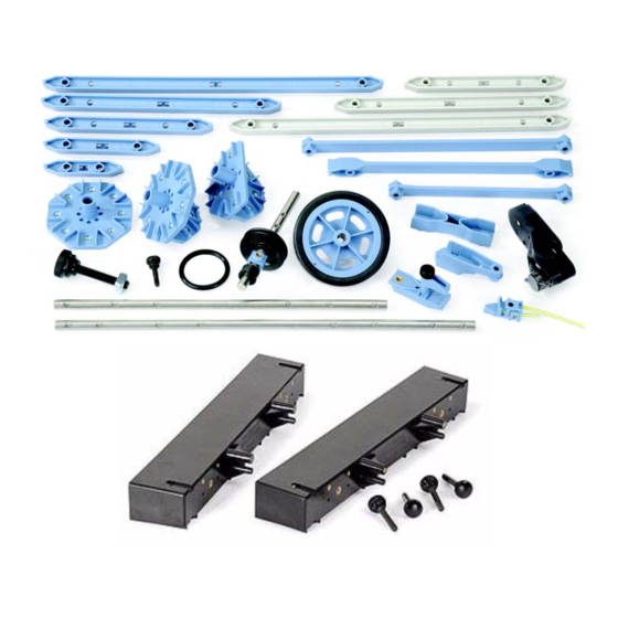
Advanced Structures Set ME-6992B Included Items Included Items 1. #5 Beam (24 cm long) 16. Drive Wheel and Tire 2. #4 Beam (17 cm long) 17. Straight Connector 3. #3 Beam (11.5 cm long) 18. Structures Rod Clamp 4. #2 Beam (8 cm long) 19. -
Page 6: Related And Recommended Equipment
The ME-6992B Advanced Structures Set is one part of the PASCO Structures System. The Advanced Structures Set can be used as a stand-alone set and it can also be combined with other parts of the PASCO Structures Sys- tem. The Load Cell and Amplifier Set (PS-2199) can be added to measure compression and tension forces in the structure members and other sets of plastic parts are available. -
Page 7: About The Components
M o d e l N o . M E - 6 9 9 2 B A b o u t t h e C o m p o n e n t s 100 N Load Cell (PS-2200) - Strain gauges mounted on a beam with no electronics so a Load Cell requires a Load Cell Amplifier (PS-2198) or Dual Load Cell Amplifier PS-2206). -
Page 8: Beam (24 Cm Long)
A d v a n c e d S t r u c t u r e s S e t A b o u t t h e C o m p o n e n t s Flat Beams 2 X 3 Flat Beams Flat Beams are used for cross-bracing. -
Page 9: Adding Load Cells
The PASCO model ME-6988A Force Platform Structures Bracket includes two brackets and four thumbscrews. The adapter bracket is designed to connect members of the PASCO Structures System to a PASCO Force Platform (not included). The brackets can also serve as foundation plates for larger structure models. -
Page 10: Properties Of I-Beams
A d v a n c e d S t r u c t u r e s S e t P r o p e r t i e s o f I - b e a m s Example: Bridge with Load Cells The bridge shown in Figure 9 incorporates six load cells to measure the tension or compression in vari-... -
Page 11: Trusses
M o d e l N o . M E - 6 9 9 2 B T r u s s e s Trusses Kingpost Truss Figure 13 shows a simple king- post truss made from #5 and #4 beams. Use a hanging mass to apply a load. -
Page 12: Common Truss Bridges
A d v a n c e d S t r u c t u r e s S e t C o m m o n T r u s s B r i d g e s Common Truss Bridges Warren Bridge The Warren Bridge (Figure 17) is a simple type of bridge consisting of a series of triangles. -
Page 13: Measuring Bridge Deflection Under Load
Using a Motion Sensor In Figure 22, the bridge is loaded by hanging a weight (Large Slotted Mass Set, PASCO Model ME-7566) from the center of the bridge. A Motion Sensor (PS-2103) is placed on the floor and pointed up toward the bottom of the weight hanger. -
Page 14: Measuring Static And Dynamic Loading
A d v a n c e d S t r u c t u r e s S e t M e a s u r i n g S t a t i c a n d D y n a m i c L o a d i n g Span a Gap Give each group a set of plastic, half of a Bridge Set or a Truss Set. -
Page 15: Forces On A Boom
M o d e l N o . M E- 6 9 9 2 B F o r c e s o n a B o o m Forces on a Boom Pulley Attach a cord from the Load Cell Half Angle Round... - Page 16 A d v a n c e d S t r u c t u r e s S e t F o r c e s o n a B o o m Forces on a Boom: Details Load Cells The “Forces on a Boom”...
-
Page 17: Human Leg Model
M o d e l N o . M E- 6 9 9 2 B H u m a n L e g M o d e l Human Leg Model Stack masses on Flat the flat connector. Connector Angle Angle Angle Connector... - Page 18 A d v a n c e d S t r u c t u r e s S e t H u m a n L e g M o d e l Human Leg Model: Details Knee Forces Directly measure the force needed to support the leg at various angles.
-
Page 19: Teeter Totter
M o d e l N o . M E- 6 9 9 2 B T e e t e r T o t t e r Teeter Totter Axle (Medium) Angle Connector Half Round Short End of Teeter Totter Detail Straight Connector Use a hanger and mass at this... - Page 20 A d v a n c e d S t r u c t u r e s S e t Te e t e r T o t t e r Teeter Totter: Details Suggestions Vary the length of the teeter totter by increasing or decreasing the number of segments or sections. Vary the placement of the pivot: it does not have to be as shown.
-
Page 21: Human Back Model
M o d e l N o . M E- 6 9 9 2 B H u m a n B a c k M o d e l Human Back Model Half Angle Connector Round Half Round Angle Load Cell Connector Angle Full Round... - Page 22 A d v a n c e d S t r u c t u r e s S e t H u m a n B a c k M o d e l Human Back Model: Details Force Vector Diagram The following diagram shows the force vectors acting on the human back model.
-
Page 23: Tower Crane
M o d e l N o . M E- 6 9 9 2 B T o w e r C r a n e Tower Crane Cord Tensioning Straight Clip Connector Cord Full Tensioning Round Half Clip Round Midsection of Crane Detail Axle (Medium) Flat... - Page 24 A d v a n c e d S t r u c t u r e s S e t T o w e r C r a n e Tower Crane: Details Extra Equipment Model Hooked Mass Set SE-8759 Force Platform PS-2141 or CI-6461...
-
Page 25: Human Arm Model
M o d e l N o . M E- 6 9 9 2 B H u m a n A r m M o d e l Human Arm Model Axle (Long) Half Round Load Full Cell Round Upper Arm Detail Angle Connector Cord Tensioning Clip... - Page 26 A d v a n c e d S t r u c t u r e s S e t H u m a n A r m M o d e l Human Arm Model: Details Extra Equipment Model Hooked Mass Set SE-8759...
-
Page 27: Angle Crane
M o d e l N o . M E- 6 9 9 2 B A n g l e C r a n e Angle Crane Half Pulley Angle Round Connector Axle (Short) Half Round Pulley Angle Connector Collet Half Round Half... - Page 28 A d v a n c e d S t r u c t u r e s S e t A n g l e C r a n e Angle Crane: Cord Details Start with a “V” loop tied to the Extra Equipment Model top axle.
-
Page 29: Catapult
M o d e l N o . M E- 6 9 9 2 B C a t a p u l t Catapult Cord Catapult Arm Detail Cord Cord Tensioning Clip Full Round Half #Straight Round Connector Full Round Use a cord to support the Catapult Arm. - Page 30 A d v a n c e d S t r u c t u r e s S e t C a t a p u l t Catapult: Details Operation Hang a 1 kg mass from the loop of cord shown in the Rear View Detail. Thread a piece of cord about 20 cm in length through a pulley and tie the cord so it makes a loop.
-
Page 31: Camelback Truss Bridge And Multilength Combinations
M o d e l N o . M E- 6 9 9 2 B C a m e l b a c k T r u s s B r i d g e Camelback Truss Bridge Angle Angle Half Half Connector... -
Page 32: Truss Bridge With Cross Bracing And Trestle With Cross Bracing
A d v a n c e d S t r u c t u r e s S e t T r u s s B r i d g e w i t h C r o s s B r a c i n g Truss Bridge with Cross Bracing Flat 4 Flat 4... -
Page 33: Pastrack Trestle With Cross Bracing
M o d e l N o . M E - 6 9 9 2 B P A S t r a c k T r e s t le w i t h C r o s s B r a c i n g PAStrack Trestle with Cross Bracing Flat Connector... -
Page 34: Tower With Cross Bracing
A d v a n c e d S t r u c t u r e s S e t T o w e r w i t h C r o s s B r a c i n g Tower with Cross Bracing Flat 4 Angle... -
Page 35: Rubber Band Powered "Car
M o d e l N o . M E - 6 9 9 2 B R u b b e r B a n d P o w e r e d “ C a r ” Rubber Band Powered “Car” Axle Angle Connector... -
Page 36: Spares Part Numbers And Summary Of Extra Equipment
A d v a n c e d S t r u c t u r e s S e t S p a r e s P a r t N u m b e r s . Spares Part Numbers. ME-6985 Flexible I-Beam Set ME-6997 Full Round (XYZ) Connectors #5 Flexible Beam (24 cm) - 16... -
Page 37: Bridges That Require An Advanced Set And A Bridge Set
The bridge models on this page feature a road bed and mini-car. These items are included in the ME-6991 Bridge Set and the ME-6995 Road Spares Set. (See the PASCO catalog or web site at www.pasco.com for more infor- mation.) Arched Causeway Bridge 2.5 meter long... -
Page 38: I-Beam Suspension Bridge Details
A d v a n c e d S t r u c t u r e s S e t I - B e a m S u s p e n s i o n B r i d g e D e t a i l s I-Beam Suspension Bridge Details The I-Beam suspension bridge requires the following: 1 Bridge Set (ME-6991) -
Page 39: I-Beam Suspension Bridge End Assembly
M o d e l N o . M E - 6 9 9 2 B I - B e a m S u s p e n s i o n B r i d g e E n d A s s e m b l y I-Beam Suspension Bridge End Assembly The following pages show details of the construction of the suspension bridge using parts from the ME-6992A Advanced Structures Set and the ME-6991 Bridge Set. -
Page 40: I-Beam Suspension Bridge Tower
A d v a n c e d S t r u c t u r e s S e t I - B e a m S u s p e n s i o n B r i d g e T o w e r I-Beam Suspension Bridge Tower The next picture shows details of the road bed assembly where it joins the first tower. -
Page 41: I-Beam Suspension Bridge Road Bed Assembly
M o d e l N o . M E- 6 9 9 2 B F l e x i b l e I - B e a m S u s p e n s i o n B r i d g e sides are joined by #3 beams. -
Page 42: Flat Beam Suspension Bridge
A d v a n c e d S t r u c t u r e s S e t F l a t B e a m S u s p e n s i o n B r i d g e Flat Beam Suspension Bridge The following shows a suspension bridge model using Flat Members for the suspension beams instead of I-Beams. -
Page 43: Cable Stayed Bridge
M o d e l N o . M E - 6 9 9 2 B C a b l e S t a y e d B r i d g e Cable Stayed Bridge The following pages show details of the Cable Stayed Bridge. Angle Connector Half... -
Page 44: Cable Stayed Bridge Details
A d v a n c e d S t r u c t u r e s S e t C a b l e S t a y e d B r i d g e Cable Stayed Bridge Details Cord Half Tensioning Clip... -
Page 45: Baltimore Bridge And Arched Causeway Bridge Details 1
M o d e l N o . M E - 6 9 9 2 B B a l t i m o r e B r i d g e Baltimore Bridge Baltimore Bridge 2.3 meter long Baltimore Bridge: Details Flat Connector Half... -
Page 46: Arch Truss Bridge
A d v a n c e d S t r u c t u r e s S e t A r c h T r u s s B r i d g e Arched Causeway Bridge Detail 2 Angle Connector Cord... -
Page 47: Cantilevered Truss Bridge
M o d e l N o . M E - 6 9 9 2 B C a n t i l e v e r e d T r u s s B r i d g e Cantilevered Truss Bridge Angle Connector Angle Connector Cross bracing... -
Page 48: Tied Arch Bridge With Cross Bracing
M o d e l N o . M E- 6 9 9 2 B T i e d A r c h B r i d g e w i t h C r o s s B r a c i n g Tied Arch Bridge with Cross Bracing Straight Connector Angle Connector... -
Page 49: Double Tied Arch Bridge With Flexible I-Beams
M o d e l N o . M E- 6 9 9 2 B D o u b l e T i e d A r c h B r i d g e w i t h F l e x i b l e I - B e a m s Double Tied Arch Bridge with Flexible I-Beams Flex 4 Flex 4... -
Page 50: Pastrack Cable Stayed Bridge
A d v a n c e d S t r u c t u r e s S e t P A S t r a c k C a b l e S t a y e d B r i d g e PAStrack Cable Stayed Bridge Use the Nut and Bolt for PAStrack to attach the PAStrack and PAStrack Curved sections... -
Page 51: Cable Stayed Bridge Construction Suggestions
M o d e l N o . M E- 6 9 9 2 B C a b l e S t a y e d B r i d g e C o n s t r u c t i o n S u g g e s t i o n s Cable Stayed Bridge Construction Suggestions Begin and Thread a cord that... -
Page 52: Resonance Structures: Beam And Tower
Sliding Connector to the middle of the I-beam. Loop a piece of yellow cord through the Cord Clip and attach the Cord Clip to the Sliding Connector. Connect the cord to the drive post. You can control the Mechanical Wave Driver with a PI-8127 Function Generator, or with a PASCO Interface and Power Amplifier. - Page 53 M o d e l N o . M E - 6 9 9 2 B R e s o n a n c e S t r u c t u r e s : B e a m a n d T o w e r Equipment Needed Part Number Mechanical Wave Driver...
- Page 54 A d v a n c e d S t r u c t u r e s S e t R e s o n a n c e S t r u c t u r e s : B e a m a n d T o w e r Measure Acceleration To measure the acceleration of the Resonance Half...
-
Page 55: Force Platform Structures Bracket
Force Platform Structures Bracket (ME-6988A) Introduction The PASCO model ME-6992B Force Platform Structures Bracket includes two brackets and four thumbscrews. The adapter bracket is designed to connect members of the PASCO Structures System to a PASCO Force Platform. Force Platform Model Number... - Page 56 3, 4, and 5 Use two thumbscrews to mount a bracket to one Use the thumb- side of a PASCO Force Platform. Note that two screws to attach brackets will fit on one Force Platform. the Bracket to a Force Platform.
- Page 57 #4 I-beam. Please refer to the instruction manuals for the PASCO Structures System Sets for ideas of what structures can be built and attached to the Force Platform Structures Bracket and a Force Platform.
-
Page 58: Technical Support, Warranty, And Copyright
PASCO scientific, is prohibited. Trademarks PASCO and PASCO scientific are trademarks or registered trademarks of PASCO scientific, in the United States and/or in other countries. All other brands, products, or service names are or may be trademarks or service marks of, and are used to iden- tify, products or services of, their respective owners.
Need help?
Do you have a question about the ME-6992B and is the answer not in the manual?
Questions and answers