Ohkura VM7000A Operation Manual
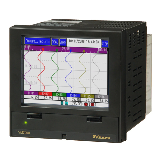
Paperless recorder
Hide thumbs
Also See for VM7000A:
- Operation manual (124 pages) ,
- Instruction manual (29 pages) ,
- Operation manual (61 pages)
Table of Contents
Advertisement
Quick Links
Download this manual
See also:
Instruction Manual
Advertisement
Table of Contents

Related Manuals for Ohkura VM7000A


Summary of Contents for Ohkura VM7000A
- Page 1 VM7000A Paperless Recorder Operation Manual WXPVM70mnA0001E October, 2009(Rev.2) All Rights Reserved, Copyright © 2009, Ohkura Electric Co.,Ltd.
- Page 2 To use this equipment safely Thank you for purchasing our VM7000A Paperless Recorder. ・ Please installs it, operates it and prepares it, after this manual is often read, and it understands enough. There is danger where the accident and the trouble occur when handling is mistaken.
- Page 3 The symbols below are used on this instrument for the cautioning information. Symbols used on the instrument This shows “Caution for handling”. This symbol is used on the parts need to reference the instruction manual for saving human body and the instrument. This shows “Protective grounding”.
- Page 4 Do not put your foot on the installed instrument or get on it, because it is dangerous. Only our serviceman or persons authorized by OHKURA are allowed to remove and Maintenance take the inner module, the main unit and printed circuit boards apart.
-
Page 5: Table Of Contents
<CONTENTS> 1. INTRODUCTION -------------------------------------------------------- 1-1 1.1 Paperless Recorder ------------------------------------------------------------------------ 1-1 1.2 Accessory check ---------------------------------------------------------------------------- 1-1 1.3 When temporarily keeping it ------------------------------------------------------------ 1-1 1.4 Confirmation of form and specification ----------------------------------------------- 1-2 1.5 Handling SD card -------------------------------------------------------------------------- 1-3 2. NAMES AND FUNCTIONS OF PARTS ---------------------------- 2-1 2.1 Names and functions of parts ----------------------------------------------------------- 2-1- 2.2 Set of O-ring for waterproof ------------------------------------------------------------ 2-3 3. - Page 6 7. SETTINF AND CHECKING PARAMETERS -------------------- 7-1 7.1 Operational mode ------------------------------------------------------------------------ 7-1 7.2 Setting and checking --------------------------------------------------------------------- 7-2 7.3 Outline of parameter setting procedure --------------------------------------------- 7-3 7.4 Basic operation of setting screens ----------------------------------------------------- 7-4 7.5 Setting the input spec -------------------------------------------------------------------- 7-7 7.6 Input CH ----------------------------------------------------------------------------------- 7-9 7.7 Calc.
-
Page 7: Introduction
1. INTRODUCTION 1.1 Paperless Recorder ① This recorder displays measured data in real time on the liquid crystal display. It is a paperless type that is also capable of saving the measured data to a SD memory card (hereinafter referred to as SD card). -
Page 8: Confirmation Of Form And Specification
1.4 Confirmation of form and specification The plaque to which the form name has been described is on the case. Please confirm this equipment is a specification the same as the order referring to the table below. 9 10 V M 7 0 A... -
Page 9: Handling Sd Card
1.5 Handling SD card Correspondence SD card is as follows. ・ Panasonic’s 1~32GB ・ SanDisk’s 1~32GB There is no SD card in this equipment. Please buy it in the computer shop etc. CAUTION ・ SD card on the market is sold having formatted it usually, therefore, it is not necessary to format it again. -
Page 10: Names And Functions Of Parts
2. NAMES AND FUNCTIONS OF PARTS Names and functions of parts ①Display Unit ②Button operation part cover Knob ① Display area The LCD is provided with touch panel. Display the measurement data and other various Parameter set screens. Touch the surface to set data. ②... - Page 11 ⑤MENU button ③Status display lamp ⑥FUNC button ④REC button ⑦SD card slot ③ Status display lamp Allow the power ON/OFF, LCD (display) ON/OFF and record status to be displayed. :Power ON, recording suspended Lamp ON (highlighted) Lamp blinks(1 sec ON/1 sec OFF):Power ON, recording in progress :Power ON, SD card writing Lamp blinks(high speed)...
-
Page 12: Set Of O-Ring For Waterproof
2.2 Set of O-ring for waterproof When the factory is shipped, O-ring for the waterproof is not installed. When the waterproof and dustproof uses it by the necessary environment, please install it according to the figure below. O-ring for waterproof It is not abnormal though the opening and shutting operation of the cover CAUTION becomes very hard if O-ring for the waterproof is installed. -
Page 13: Installation
3. INSTALLATION 3.1 Installation place Install place This equipment is a structure that is installed in the panel and used. Please choose and install the following places. ・ Place without vibration and impact. ・ Place where dust and causticity gas are few. Place where ambient temperature doesn't exceed 0 ~... -
Page 14: Terminal Stand Array And Lan Connector
4. WIRING 4.1 Terminal stand array and LAN connector The terminal stand is one row in the uppermost part, and 4 rows or less are in the lower side for the analog input and option. The part of “Terminal No.41 49”... -
Page 15: Wiring For Power Supply
4.2 Wiring for power supply Wiring for power supply Warning Please energize to this equipment after doing the protection earth without fail for the ① electric shock prevention. Please do not cut the protective earth, and please do not remove connecting wires of the ②... -
Page 16: Wiring For Analog Input
4.3 Wiring for analog input CAUTION Notes of input wire ① ・ Please do not mix the noise about the input wiring. Moreover, the use of an effective shield line or twist line is recommended to the noise in the input wiring. ・... -
Page 17: Wiring For Com Alm
4.4 Wiring for COM ALM COM ALM can be used as an alarm output of measurements etc. [Schematic diagram] Load +5~30V Open collector output(1 point) Point of contact ratings:30V DC 20mA/1 point 4.5 Wiring for LAN cable [Communication specification] Specification 10BASE-T Transmission speed 10Mbps... -
Page 18: Wiring For Di/Do (Option)
4.6 Wiring for DI/DO (Option) DI/DO becomes a connector joint. DI/DO connector [Pin array] Pin No. Signal name Pin No. Signal name DO10 DO11 DO12 DI_COM DO_COM DI_COM DO_COM DI_COM DO_COM DI_COM DO_COM DI_COM DO_COM DI_COM DO_COM DI_COM DO_COM DI_COM DO_COM... -
Page 19: Wiring For Relay Output (Option)
[DI schematic diagram] Wireless pressure point of contact input(9 point), common Ratings:Photo coupler drive 12V DC about 3mA/1 point [DO schematic diagram] Load +5~30V Open collector output(12 point), common Point of contact ratings:30V DC 20mA/1 point 4.7 Wiring for relay output (Option) Terminal RL:Relay output(6 points) Contact capacity:3A/250V AC, 3A/30V DC (3A/1 common, Total 9A or less)... -
Page 20: Operation
5. OPERATION 5.1 Before operating Please confirm the installation of SD card (Refer to item 1.5), wiring (Refer to item 4) before it operates. Afterwards, please confirm the various parameter settings (Refer to item 7). 5.2 Start and stop of record The record begins when REC button is pushed. -
Page 21: Display Function
6. DISPLAY FUNCTION 6.1 Basic composition of data display screen ④Graph type ①Group screen name ③Change trend ②Clock display ⑤Change display ⑥Scale display ⑦Data display area ⑩Event flag display area ⑧Measured value display area ⑭Sub record display ⑬Main record display ⑨Event display area ⑮Internal memory ⑪SD card loading /... - Page 22 Data display area ⑦ Allow the Real time trend display, Historical trend display, Bar graph display, Digital display and Event history / communication history display to be displayed. (Refer item 6.2 to 6.6) Display measured data at the position of the cursor when Historical trend display. Measured value display area ⑧...
- Page 23 Event display area ⑨ Event information such as beginning to record is displayed. Event flag display area ⑩ The time when warning has been generated belt is red; the time when the event of the message etc. has been generated belt is displayed in green. SD card loading / writing status display ⑪...
-
Page 24: Real Time Trend Display Of Measured Data
6.2 Real time trend display of measured data [Explanation] The measured data can be display in graph. The vertical or horizontal trend directions can be selected by touching to GRPH key. The refreshment cycles of graph synchronizes record cycles. Horizontal trend Vertical trend Time (H : M : S) -
Page 25: Digital Display Of Measured Data
6.4 Digital display of measured data [ Explanation] The measured data can be display in digital graph. [Operation] The measured data can be changed digital graph by touching the GRPH key several times. Channel No. ①Unit ②Display of measured value ③Alarm No. -
Page 26: Historical Trend Display
6.5 Historical trend display [Explanation] The past data of currently recoding data or the data saved in the past can be read and displayed. [Operation] Press the REAL key on the Real time trend display, and the following display appears. ①Cursor date ②Cursor ⑦Measured value... - Page 27 File select key ⑥ The data saved in the past can be read and displayed. Folder group File group When you select an arbitrary folder from among the “Folder group”, the file data included in the folder is displayed in the file group. When select an arbitrary file, and touching the OK key, on the historical trend screen, the data preserved in the past is read and displayed.
-
Page 28: Event History / Communication History Display
6.6 Event history / communication history display [Explanation] When a specific event is generated in the data recording now, it is possible to make a mark. The history of LAN communication is preserved. [Operation] The event history display can be displayed by touching the GRPH key several times. And, the screen can be changed communication history display by touching the DISP key several times. -
Page 29: Settinf And Checking Parameters
7. SETTING AND CHECKING PARAMETERS 7.1 Operational mode [Explanation] This Paperless Recorder can do a more detailed setting by setting the “Operation mode” to “Advanced mode” on the parameter setting screen and the system setting screen. [Operation] Touch the MENU button System Device/Other Mode... -
Page 30: Setting And Checking
7.2 Setting and checking Main menu ① The menu display can be displayed by pressing MENU button. The parameter setting display can be displayed by select “Parameter” touching. Back key when touching, it returns to the trend screen. Back key Main menu Parameter setting Sub menu... -
Page 31: Outline Of Parameter Setting Procedure
7.3 Outline of parameter setting procedure Data display screen Menu screen MENU Page Parameter … 7-9 Input CH Input Input setting screen … 7-9 Scaling Scaling setting screen … 7-9 Display Display setting screen … 7-10 Scale setting screen Scale …... -
Page 32: Basic Operation Of Setting Screens
7.4 Basic operation of setting screens [Explanation] The basic operation of the setting screens is classified in the following methods. To move a set item, the corresponding item is touched. Item into which set content whenever touching changes ① In this case, OFF when touching, it changes with Instant value Average Max/Min ⇒... - Page 33 When selecting contents to set from list. ③ The item displayed in the list is selected touching. The scroll bar is displayed when there is a selection item that exceeds the size of the screen. The display can be changed by touching arrow key ( ) or sliding scroll bar.
- Page 34 Character Entry box ① The input character is displayed. Alphabet key ② The capital letters and small letters can be changed. Numerical value key ③ The numerical value input can be changed. Symbol key ④ The symbol input can be changed. Del key ⑤...
-
Page 35: Setting The Input Spec
7.5 Setting the input spec [Explanation] For select of the input types for each channel (thermocouple, resistance bulb and DC voltage input), and the presence of Burn Out function can be set. Note: When the recorder is in recording, the “Input type” cannot be changed. [Operation]... - Page 36 Burn Out ③ Setting the Burn Out function.(The record swings over to the 0% side or the 100% side) Burn Out function can only be set when the input type is “TC” and “mV”. ④ The method of making amends for the temperature of the terminal of the thermo-couple cooking stove is selected.
-
Page 37: Input Ch
7.6 Input CH 6 Input CH [Explanation] [Explanation] Various settings concerning the input channel are done. Various settings concerning the input channel are done. [Reference] [Reference] When the operational mode is only an advanced mode, the item that “ When the operational mode is only an advanced mode, the item that “ is attached to “Advanced”... - Page 38 [Scale] Item Setting contents Advanced Select the channel number. When “0” is input, it displays it according Channel to the scale display automatically. Range of scale Input the range of scale. Partitions Input the value of partitions. ○ [Alarm value] Item Setting contents Advanced...
-
Page 39: Calc. Ch
7.7 Calc. CH 7 Calc. CH The operational expression and the more details setting of the operation channel can be set with the The operational expression and the more details setting of the operation channel can be set with the parameter loader software. - Page 40 [Alarm action] Item Setting contents Advanced Channel Select the channel number. ○ Hysteresis ( ) Input the value of Hysteresis. ○ Input the value of Alarm delay. Alarm Delay(sec) ○ [REC/CALC] Item Setting contents Advanced Channel Select the channel number. ○...
-
Page 41: Display
7.8 Display In the “Display”, it is possible to set it variously concerning the display of the measuring data. [Group name] Item Setting contents Advanced Group Select the group number. Display name Set the display name. TAG disp set Select the TAG display set. Select the display “ON”, “OFF”. -
Page 42: Record
7.9 Record .9 Record In the record setting, it is possible to set it variously concerning the record of the measuring data. In the record setting, it is possible to set it variously concerning the record of the measuring data. [Setting(Main)]... -
Page 43: Others
7.10 Others [Unit] Item Setting contents Advanced Unit The edit display of new unit can be moved by touching “Add”. [Message] Item Setting contents Advanced Message No. Select the Message number. ○ Message Input the Message. ○ Timing Select the timing of message is displayed. ○... -
Page 44: Outline Of System Setting Procedure
8. SETTING AND CHECKING SYSTEMS 8.1 Outline of system setting procedure Page … 8-2 SD remove SD card writing screen System SD/Param … 8-2 SD format SD card format screen … 8-2 Param save Setting value saving screen … 8-2 Param load Setting value loading screen …... -
Page 45: Sd / Param
8.2 SD / Param [SD remove] Please execute it before taking out the SD card. Item Setting contents Advanced The current measuring data is written to the SD card while recording SD remove and the SD card can be taken out. The record is continued. [SD format]... -
Page 46: Comm
8.3 Comm. [Ethernet1] Item Setting contents Advanced IP Address Input the IP Address. Subnet Mask Input the Subnet Mask. Default GW Input the Default GW. DNS address Input the DNS address. MAC address Display the MAC address. [Ethernet2] Item Setting contents Advanced ○... - Page 47 [FTP] Item Setting contents Advanced User name Input the user name. Password Set the password. (Cannot use space character in password.) Level Select the level. [Modbus] Item Setting contents Advanced ○ Operation Select the operation of Modbus. Station No. Input the value of station number. Modbus TCP Input the time until timeout.
-
Page 48: Device / Other
8.4 Device / Other [LCD] Item Setting contents Advanced Sleep time(min) Input the value of sleep time. Input the value of LCD active brightness. It lightens by the numerical Act. brightness value large. Input the value of LCD sleep brightness. It lightens by the numerical Sleep brightness value large. -
Page 49: Engineering
8.5 Engineering [ Explanation] This item is for the factory coordination. Please do not change the setting. -
Page 50: Specification
9. SPECIFICATION 9.1 Basic specification •Number of inputs:Selection from 3,6,9,12 points.(Immediately after purchase) •Input circuit:Inputting mutual insulation. •Measuring period:100mm sec •Input type: Direct voltage, direct current (shunt resistance of necessity), TC and RTD •Changing of input type: Setting from set menu displayed with front side MENU button. •Burnout function:... -
Page 51: Measurement Range
9.2 Measurement range Range Measurement Type Accuracy rating Remarks code range Resolution -10.00 ~ +10.00 10μV 0.00 ~ +20.00 10μV 0.00 ~ +50.00 10μV -0.200 ~ +0.200 ±(0.1%+1digit) -1.000 ~ +1.000 -10.00 ~ +10.00 10mV 0.000 ~ +5.000 4.00 ~ 20.00 0.01mA B *1 0.0 ~... -
Page 52: Display Part
9.3 Display part •Indicator: 5.7 inch TFT color LCD(320×240 dot) The touch panel, back light is applied. The brilliance control is possible. The pixel that always lights partially or doesn't light the liquid crystal display might exist. And, it is not a breakdown though the irregularity of brightness might be caused. Please acknowledge it beforehand. -
Page 53: Record Function
9.5 Record function •External recording medium: SD memory card(It corresponds to the SD/SDHC standard) •Internal memory:About 100MB •Record capacity: SD standard:2GB or less SDHC 規格:32GB or less •Record method: The record begins by turning on the REC button. It records by the new file name at the time of each record beginning. -
Page 54: Alarm Function
•SD memory card: Confirmed operation SD memory card: ・Panasonic company 1~32GB ・Sandisk company 1~32GB Please buy it in the computer shop etc. •Data format: It is possible to select it from either of method of the binary or binary + CSV. ( It is not possible to change while recording. -
Page 55: Power Supply Part
9.8 Power supply part • Rated supply voltage :100~240V AC • Range of use voltage :85~264V AC • Power supply frequency:50/60Hz(Sharing) • Power consumption: Power-supply Power consumption voltage Usually LCD OFF ※ 100V AC Under 15VA Under 12VA 240V AC Under 25VA Under 22VA When you “OFF”... -
Page 56: Compatible Specification
9.12 Compatible specification •CE: EMC instruction:EN61326-1 compatible Low Voltage Directive:EN61010-1 適合 • Dustproof and waterproof standard: JIS C0920 IP65(Front panel)conforming 9.13 Transportation and storage conditions • Temperature:-10~60℃ • Humidity:5~90%RH • Vibration:Under 10~60Hz 2.45m/s • Impact:Under 249m/s (State of packing) 9.14 Optional function(Option) ■Communication RS-485 communication module can be mounted. -
Page 57: Support Software
•DO output : Open collector output(12 points), Common Point of contact ratings:30V DC 20mA/1 point It is possible to specify it for an alarm output. ■Relay output (The 9th form digit code “2”) Only one card with the output of the relay of 6 points can be mounted. However, when the number of inputs is 12 points or DI/DO card selection, it is not possible to mount. -
Page 58: Externals Size
9.16 Externals size <Panel cutting>...
Need help?
Do you have a question about the VM7000A and is the answer not in the manual?
Questions and answers