
Related Manuals for GNB FURY X-3


Summary of Contents for GNB FURY X-3
- Page 1 INSTALLATION AND OPERATING INSTRUCTIONS FOR FURY X-3™ DEDICATED FAST CHARGER FOR INDUSTRIAL BATTERIES...
- Page 2 NOTE This document is based on information available at the time of its publication. While efforts have been made to be accurate, the information contained herein does not purport to cover all details or variations in hardware or software, nor to provide for every possible contingency in connection with installation, operation, or maintenance.
-
Page 3: Table Of Contents
CONTENTS Fury X-3 Features and Benefits Technical Specifications Safety Precautions Installation Wall Mount Installation Floor Stand Installation Connection to Main Power Operating Instructions Control Panel Features Charger Operation Viewing Charger and Charging Information Main Menu Eq/Mix Actuals Records Settings Info (System Information) -
Page 4: Fury X-3 Features And Benefits
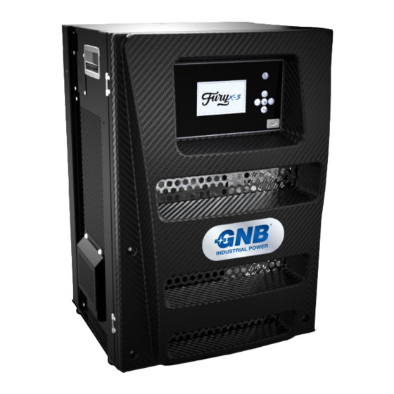
FURY X-3 FEATURES AND BENEFITS The Fury X-3 charger is a multi-voltage modular design for industrial battery fleet applications. It uses Silicon Carbide MOSFET (Metal Oxide Semiconductor Field-Effect Transistor) power technology to provide efficient high frequency power conversion to minimize infrastructure costs, reduce your carbon footprint and provide multi-shift standard, opportunity and fast charging capabilities. -
Page 5: Technical Specifications
Wireless configuration, communication, and control capabilities via Bluetooth , Wi-Fi and PLC, USB port ® Field Repair Module Replacement Installation Wall, stand, or shelf mounting options * Stated output currents will require connectors and electrical cables of adequate capacity Fury X-3 Installation and Operating Instructions... -
Page 6: Safety Precautions
Never place the charger directly above or below the battery being charged; gases or fluids from the battery will corrode and damage the charger. Locate the charger as far away from the battery as DC cables permit. Fury X-3 Installation and Operating Instructions... - Page 7 Ne jamais placer le chargeur directement au-dessus ou au-dessous de la batterie en charge; les gaz et les fluides de la batterie corroderaient et endommageraient le chargeur. Placer le chargeur aussi loin de la batterie que le permettent les câbles CC. Fury X-3 Installation and Operating Instructions...
-
Page 8: Installation
Bottom Step 3. Mount the Bottom Brace to the Charger and Wall Step 4. Mount the Pogo Wall Bracket to the Wall and Attach the Pogo Fury X-3 Installation and Operating Instructions... -
Page 9: Floor Stand Installation
Hang the charger on the floor mount hanger so that the two slits on the back of the charger line up with the two fins of the hanger. Step 4. Mount the Bottom Brace to the Charger and Stand Fury X-3 Installation and Operating Instructions... -
Page 10: Connection To Main Power
Ground ends of the ground and power cables. Retighten the screws. The 3-phase input is not phase specific, so AC line input positions are interchangeable. Ensure cable or conduit clamp has been properly tightened. Fury X-3 Installation and Operating Instructions... - Page 11 5.3 to 53.5 SBE® 320 / SBX® 350 1/0 to 300 mcm 53.5 to 152 NOTE: Many of the mm² wire sizes are based on calculations. See the catalog for specific mm² wire sizes. Fury X-3 Installation and Operating Instructions...
-
Page 12: Operating Instructions
If a battery is connected, the Press Start Screen is displayed. Press the START/STOP button to begin charging. If AutoStart is enabled, the charger will begin charging automatically after a 10 second countdown when a battery is connected to the unit. Fury X-3 Installation and Operating Instructions... - Page 13 There is also the option to view charge details by pressing the down arrow. The details screen provides the same information as the record detail screen. Fury X-3 Installation and Operating Instructions...
-
Page 14: Viewing Charger And Charging Information
Select a record by using the Up and Down arrow keys. To view a selected record details, press the center key. Use the left arrow key to go back to the previous screen. Fury X-3 Installation and Operating Instructions... -
Page 15: Settings
Note: the Set Time Menu uses a 24-hour clock. Info (System Information) This screen displays the following information about the charger: Type Kilowatt rating Serial number Max output current Application version Cable configuration Drawer quantity Voltage setting Fury X-3 Installation and Operating Instructions... -
Page 16: Usb
To find more information on the error, press the down arrow on the navigator to access the Error Details screen. For service, please contact your local sales representative. Fury X-3 Installation and Operating Instructions... - Page 17 Termination Block bottom of the charger. Then, unplug the communications starting from the bottom power module until you have disconnected the module you are replacing. Fury X-3 Installation and Operating Instructions...
- Page 18 Reconnect all communication cables that were disconnected in step 3. Reconnect ground , DC output, and AC input cables. Close charger door and use flat head screw driver to turn the latch counter-clockwise to lock. Fury X-3 Installation and Operating Instructions...
-
Page 19: Index
Mix 11 Module Error 13 MOSFET 1 Operating Instructions 9 Records 11 Safety 3 Service and Troubleshooting 13 Settings 12 Specifications 2 System Error 13 Fury X-3 Installation and Operating Instructions ©2018 Exide Technologies Exide Technologies Milton, GA 30004. GB5080 08/18...
Need help?
Do you have a question about the FURY X-3 and is the answer not in the manual?
Questions and answers