
Related Manuals for BK Precision 4050B Series


Summary of Contents for BK Precision 4050B Series
- Page 1 4050B Series Function/Arbitrary Waveform Generator USER MANUAL 1.800.561.8187 information@itm.com www. .com...
- Page 2 Safety Summary The following safety precautions apply to both operating and maintenance personnel and must be followed during all phases of operation, service, and repair of this instrument. Before applying power to this instrument: Read and understand the safety and operational information in this manual. ...
- Page 3 Category IV (CAT IV): Measurement instruments whose measurement inputs are meant to be connected to the primary power entering a building or other outdoor wiring. Do not use this instrument in an electrical environment with a higher category rating than what is specified in this manual for this instrument.
- Page 4 Unless otherwise stated, a ground connection on the instrument's front or rear panel is for a reference of potential only and is not to be used as a safety ground. Do not operate in an explosive or flammable atmosphere Do not operate the instrument in the presence of flammable gases or vapors, fumes, or finely- divided particulates.
- Page 5 Measurements made by this instrument may be outside specifications if the instrument is used in non-office-type environments. Such environments may include rapid temperature or humidity changes, sunlight, vibration and/or mechanical shocks, acoustic noise, electrical noise, strong electric fields, or strong magnetic fields. Do not operate instrument if damaged If the instrument is damaged, appears to be damaged, or if any liquid, chemical, or other material gets on or inside the instrument, remove the instrument's power cord, remove the...
- Page 6 Do not touch live circuits Instrument covers must not be removed by operating personnel. Component replacement and internal adjustments must be made by qualified service-trained maintenance personnel who are aware of the hazards involved when the instrument's covers and shields are removed. Under certain conditions, even with the power cord removed, dangerous voltages may exist when the covers are removed.
- Page 7 Cooling fans This instrument contains one or more cooling fans. For continued safe operation of the instrument, the air inlet and exhaust openings for these fans must not be blocked nor must accumulated dust or other debris be allowed to reduce air flow. Maintain at least 25 mm clearance around the sides of the instrument that contain air inlet and exhaust ports.
-
Page 8: Compliance Statements
Compliance Statements Disposal of Old Electrical & Electronic Equipment (Applicable in the European Union and other European countries with separate collection systems) This product is subject to Directive 2002/96/EC of the European Parliament and the Council of the European Union on waste electrical and electronic equipment (WEEE), and in jurisdictions adopting that Directive, is marked as being put on the market after August 13, 2005, and should not be disposed of as unsorted... - Page 9 CE Declaration of Conformity This instrument meets the requirements of 2006/95/EC Low Voltage Directive and 2004/108/EC Electromagnetic Compatibility Directive with the following standards. Low Voltage Directive o EN61010-1: 2001 EMC Directive o EN 61000-3-2: 2006 o EN 61000-3-3: 1995+A1: 2001+A2: 2005 o EN 61000-4-2 / -3 / -4 / -5 / -6 / -11 o EN 61326-1: 2006 viii...
-
Page 10: Safety Symbols
Safety Symbols Refer to the user manual for warning information to avoid hazard or personal injury and prevent damage to instrument. Electric Shock hazard Alternating current (AC) Chassis (earth ground) symbol. Ground terminal On (Power). This is the In position of the power switch when instrument is ON. -
Page 11: Table Of Contents
Table of Contents SAFETY SUMMARY ..............................I ............................OMPLIANCE TATEMENTS ................................AFETY YMBOLS ................................. OTATIONS GENERAL INFORMATION .......................... 1 ............................1 RODUCT VERVIEW ............................. 1 ACKAGE ONTENTS ............................3 RONT ANEL VERVIEW Front Panel Description ........................... 3 ............................4 ANEL VERVIEW Rear Panel Description ............................ - Page 12 Selecting Modulation Source ............................ 43 To Set Modulation Depth ............................44 To Set Modulation Frequency ........................... 44 DSB-AM Modulation ............................44 FM Modulation .............................. 46 To Set Frequency Deviation ............................47 PM (Phase Modulation) ..........................47 To Set Phase Deviation .............................. 48 FSK Modulation .............................
- Page 13 ................................77 UTPUT Load ................................78 Polarity ................................78 EqPhase ................................. 79 Combining Waveforms (Wave Combine) ...................... 79 CH C ............................80 OUPLING Channel Copy ..............................80 Channel Coupling ............................81 Frequency Coupling ..............................82 Amplitude Coupling ..............................82 Phase Coupling ................................83 Tracking .................................
- Page 14 Example 8: Generate a Burst Waveform ..................... 110 Example 9: Generate an AM Modulation Waveform .................. 112 Example 10: Generate an FM Modulation Waveform ................113 Example 11: Generate a PM Modulated Waveform ................... 114 Example 12: Generate an FSK Modulated Waveform ................. 115 Example 13: Generate an ASK Modulation Waveform ................
-
Page 15: General Information
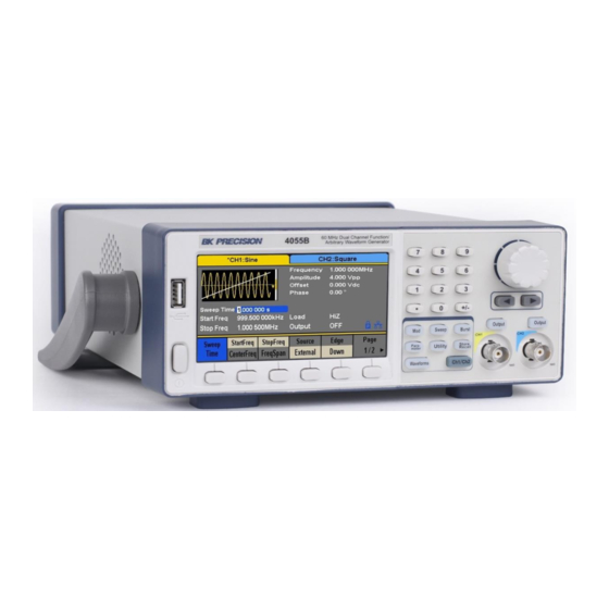
General Information 1.1 Product Overview BK Precision’s 4050B series are dual-channel function/arbitrary waveform generators, capable of generating sine and square waves of up to 10 MHz, 30 MHz or 60 MHz (depending on model). They have an informative easy-to-read color display, user-friendly controls and a numeric keypad which allows users to easily configure waveform properties. - Page 16 1 x 4050B series function/arbitrary waveform generator 1 x Getting started manual (printed) 1 x AC power cord 1 x USB type A to Type B cable 1 x Certificate of calibration Verify that all items above are included in the shipping container. If anything is missing, please contact B&K Precision.
-
Page 17: Front Panel Overview
1.3 Front Panel Overview Front Panel Description Power On/Off switch Menu softkeys Menu buttons Channel 1 output terminal Channel 2 output terminal Channel 1 and 2 Output On/Off buttons Arrow keys Rotary dial knob Numeric keypad TFT LCD color display USB host port/*USB-to-GPIB adapter interface Accepts USB flash drive to save/recall instrument settings and waveforms. -
Page 18: Rear Panel Overview
1.4 Rear Panel Overview Rear Panel Description LAN Interface USB interface AC Power Input Chassis ground 10MHz Out BNC connector Aux In/Out BNC connector Counter BNC Connector 1.800.561.8187 information@itm.com www. .com... -
Page 19: Display Overview
1.5 Display Overview Display Description Waveform display Channel status bar Waveform parameters display Waveform mode and output impedance indicator LAN status indicator Mode phase locked/free running indicator Menu display Waveform parameters display 1.800.561.8187 information@itm.com www. .com... -
Page 20: Getting Started
Getting Started Before connecting and powering up the instrument, please review and go through the instructions in this chapter. 2.1 Input Power Requirements Input Power The supply has a universal AC input that accepts line voltage and frequency input within: 100 –... -
Page 21: Impedance Matching
1. Use good quality 50 Ω coaxial cable and connectors. 2. Make all connections tight and as short as possible. 3. Use good quality attenuators, if it is necessary to reduce waveform amplitudes applied to sensitive circuits. 4. Use termination or impedance-matching devices to avoid reflections. 5. -
Page 22: Check Model And Firmware Version
Figure 1 - Preliminary Self-Test Figure 2 - Self-Test Options Note: Refer to TEST/CAL section for more information about the Self-Test function. Check Model and Firmware Version The model and firmware version can be verified from within the menu system. Press Utility, press System select and press Page 1/2 from the menu to enter the second menu page, and select System Info option. -
Page 23: Output Check
Output Check Follow the steps below to do a quick check of the settings and waveform output. 1. Turn on the instrument and set the instrument to default settings. To set to default, press Utility → System → Set To Default to set the system to the default setting. The instrument will set both channels with the following parameters: Output Default... - Page 24 Start Phase 0° Cycles 1 Cycle Trig Out Delay 521 ns Trigger Default Source Internal Table 1 - Default Settings 1. Connect the BNC output of CH1 (yellow) into an oscilloscope. 2. Press the Output button on top of CH1 output BNC to turn on the output and observe a sine wave with the parameters above.
-
Page 25: Front Panel Operation
3 Front Panel Operation 3.1 Menu Options All settings and parameters can be configured from the menu system of the instrument. The channel specific menu options are the same for both channel 1 and channel 2. Use the Ch1/Ch2 button keys to toggle the channel selection. The selected option will be highlighted in blue. - Page 26 Offset/LowLevel Configures the DC offset or the low level of the waveform. Phase Configures the phase relative to the other channel. DutyCycle Configures the duty cycle of the waveform. Ramp Frequency/Period Configures the frequency or period of the waveform. Amplitude/HighLevel Configures the amplitude or the high level of the waveform.
- Page 27 Source Selects modulating source. AM Depth Set the modulation depth. Shape Configures the modulating waveform shape. AM Freq Set the modulating waveform frequency. Frequency range: 1 mHz to 20 kHz (internal source only). Sweep Sweep Time Configures the sweep time for sweep output. StartFreq/CenterFReq Configures the sweep start frequency or the center frequency.
-
Page 28: Selecting A Channel
Copy channel settings between channels. 3.2 Selecting a Channel The 4050B series function/arbitrary waveform generators have dual channel outputs. They can be operated independently or in sync with each other. To select between channel 1 and 2 and view/change their parameters, press the Ch1/Ch2 key. -
Page 29: Configure Waveform Output
Figure 4 - Channel 2 Selected 3.3 Configure Waveform Output Configure Waveform Shape The instrument can generate many standard as well as arbitrary waveforms. There is a dedicated waveform key on the front panel that will allow the user to select between different waveform shapes to output, as listed in Table 4. - Page 30 Press Waveforms to select a waveform. Menu options relevant to the selected waveform shape will display at the bottom of the screen. The screenshots below illustrates the menu options for each of the waveform types. Sine Waveform Square Waveform Ramp Waveform Pulse Waveform Noise Waveform DC Waveform...
-
Page 31: Configure Frequency
Table 5 - Waveforms Configure Frequency This section does not apply to noise or DC waveforms. Press the Frequency/Period softkey to toggle between the Frequency and Period settings. The option selected will be highlighted in blue. The current value for the waveform’s frequency or period is now highlighted on the Waveform Parameters display section of the screen. -
Page 32: Configure Amplitude
4. Use the menu function keys to select the unit. Available units are: MHz, kHz, Hz, mHz, and uHz. Note: When using the numeric keyboard to enter the value, the left arrow key can be used to move the cursor backward and delete the previous digit. Configure Amplitude This section does not apply for noise or DC waveform. -
Page 33: User-Defined High And Low Level
User-Defined High and Low Level The user has the option to adjust the high and low level of the waveform. To do this, toggle the menu function key from Amplitude to HighLevel and the LowLevel option will be available as well. -
Page 34: Configure Phase
Figure 8 - Offset 6. Use the menu function keys to select the unit. Available units are: Vdc and mVdc. Configure Phase This section does not apply for pulse, noise, or DC waveforms. The Phase setting is useful for adjusting the phase relationship between channels 1 and 2, between a channel and its sync signal, and synchronizing multiple instruments. -
Page 35: Configure Duty Cycle: Square Waveform
Figure 9 - Phase 6. Use the menu function keys to select the degree (°) unit. Note: When the IndependentMode is enabled, the phase parameter cannot be modified (i.e., the phase can only be set when there is a reference clock waveform provided on the back panel). Configure Duty Cycle: Square Waveform Figure 10 - Duty Cycle The duty cycle setting range is limited by the “Frequency/Period”... -
Page 36: Configure Width And Duty Cycle: Pulse Waveform
Figure 11 - Duty Cycle of a Square Waveform 4. Use the menu function keys to select the degree (°) unit. Configure Width and Duty Cycle: Pulse Waveform The pulse width and duty cycle parameters are related to each other and both control the length of the “On Time”... -
Page 37: Configure Rise/Fall Edge: Pulse Waveform
Follow the steps below to configure the pulse width or duty cycle. 1. Press the Waveforms button. 2. Press the Pulse softkey. 3. Select PulWidth softkey for pulse width adjustment or DutyCycle for duty cycle adjustment. 4. The cursor position will now highlight the first digit of the width or duty parameter display. -
Page 38: Configure Delay: Pulse Waveform
3. Toggle the Rise/Fall softkey to set the rise or fall edge. The Rise/Fall softkey lets the user toggle between the Rise and Fall Edge settings. The selected setting will be highlighted in blue. Use the numeric keyboard to input the parameter value directly and press the corresponding key to select the parameter unit. -
Page 39: Configure Symmetry: Ramp Waveform
Figure 16 - Pulse Delay 4. Use the rotary knob or the numeric keypad to change the pulse delay. After entering the numeric value, use the menu function keys to select s, ms, us, or ns. Configure Symmetry: Ramp Waveform A ramp waveform with 50% of symmetry is a triangular waveform. -
Page 40: Configure Standard Deviation And Mean: Noise Waveform
Figure 18 - Ramp Symmetry 4. Use the rotary knob or the numeric keypad to change the symmetry. 5. Once the value has been entered, press the “%” softkey from the menu to set the value. Configure Standard Deviation and Mean: Noise Waveform There are two parameters that can be adjusted of the noise waveform: Standard deviation and mean. -
Page 41: Configure Offset: Dc Waveform
Figure 19 - Noise Standard Deviation Figure 20 - Noise Mean 5. Use the rotary knob or the numeric keypad to change the two parameters. Both parameters can be specified in V or mV units. Configure Offset: DC Waveform The instrument can output a DC waveform output at a range of voltage levels (-12 Vdc – 12 Vdc). -
Page 42: Configure Arbitrary Waveforms
2. Select and press the DC waveform softkey from the menu. 3. The cursor position will now be highlighted the first digit of the DC offset parameter display. Figure 21 - DC Offset 4. Use the rotary knob or the numeric keypad to change the two parameters. Both parameters can be specified in Vdc or mVdc units. - Page 43 Waveform Function Waveform Function StairUp Stair-up waveform Npulse Negative pulse StairDn Stair-down waveform UpRamp UpRamp waveform Stair-up and down StairUD DnRamp DnRamp waveform waveform Trapezia Trapezia waveform SineTra Sine-Tra waveform Ppulse Positive pulse SineVer Sine-Ver waveform Arbitrary Waveform: Math Waveform Function Waveform Function...
- Page 44 Arbitrary Waveform: Engine Waveform Function Waveform Function Cardiac Cardiac signal SCR firing profile Quake Analog quake waveform TV signal Chirp Chirp signal Voice Voice signal TwoTone TwoTone signal Surge Surge signal SNR signal Radar Analog radar signal AmpALT Gain oscillation curve Ripple Ripple wave of battery Attenuation oscillation...
- Page 45 Kaiser Kaiser window BohmanWin BohmanWin window Blackman Blackman window ChebWin ChebWin window GaussiWin GaussiWin window FlattopWin Flat top weighted window Triangle window (Fejer Triangle ParzenWin ParzenWin window window) BlackmanH BlackmanH window TaylorWin TaylorWin window TukeyWin (tapered cosine) Bartlett-Hann Bartlett-Hann window TukeyWin window Arbitrary Waveform: Trigonometric (Trigo)
- Page 46 Square waveform with 2% Square waveform with 38% SquareDuty02 SquareDuty38 duty duty Square waveform with 4% Square waveform with 40% SquareDuty04 SquareDuty40 duty duty Square waveform with 6% Square waveform with 42% SquareDuty06 SquareDuty42 duty duty Square waveform with 8% Square waveform with 44% SquareDuty08 SquareDuty44...
- Page 47 Arbitrary Waveform: Square 2 Waveform Function Waveform Function Square waveform with 70% Square waveform with 86% SquareDuty70 SquareDuty86 duty duty Square waveform with 72% Square waveform with 88% SquareDuty72 SquareDuty88 duty duty Square waveform with 74% Square waveform with 90% SquareDuty74 SquareDuty90 duty...
- Page 48 ECG3 Electrocardiogram ECG15 Electrocardiogram 15 Waveform of the low ECG4 Electrocardiogram LFPulse frequency pulse electrotherapy Waveform 1 of the nerve ECG5 Electrocardiogram Tens1 stimulation electrotherapy Waveform 2 of the nerve ECG6 Electrocardiogram Tens2 stimulation electrotherapy Waveform 3 of the nerve ECG7 Electrocardiogram Tens3...
- Page 49 Follow the steps below to browse and select a predefined arbitrary waveform. 1. Press the button. Waveforms 2. Go to the second page of waveform options by pressing the 1/2 softkey. 3. Select and press the Arb softkey from the menu. Figure 22 - Arbitrary Waveform 4.
-
Page 50: Generate User-Defined Waveforms
5. Once selected, press the knob to confirm and set the waveform or navigate to page 3/3 and press the Accept option from the menu. 6. The generator will return to the main Arb parameter menu and the waveform display area will show the waveform shape of the selected predefined arbitrary waveform. - Page 51 1. Setup Press the Waveforms button. 2. Go to the second page of waveform options by pressing the 1/2 softkey. Select and press the Arb softkey from the menu. 3. Press Arb Type and select Stored Waveforms to see a list of all arbitrary waveform files created and loaded from EasyWave software.
-
Page 52: Configure Harmonic Generator
6. Use the knob to navigate to the file and either press the Recall softkey or press the knob to load the waveform. If the waveform is sent to the unit using EasyWave, the file will be saved to the internal memory. - Page 53 Figure 27 - Harmonic Generator Item Menu Function Type Set the harmonic type to “odd”, “ever” or “all”. Order Set the order of the harmonic. Harmonic Set the amplitude of the harmonic. Ampl Harmonic Set the phase of the harmonic. Phase Return Return to the sine parameters menu.
-
Page 54: Configure Modulation Output
1. Press Order. The range is limited by the maximum output frequency of the instrument and current fundamental waveform frequency. Range: 2 to maximum output frequency of the instrument ÷ current fundamental waveform frequency The maximum is 10. 2. -
Page 55: Am Modulation
source (internal/external), depth, modulating frequency, modulating waveform and carrier. DSB-AM source (internal/external), modulating frequency, modulating waveform and carrier source (internal/external), modulating frequency, frequency deviation, modulating waveform and carrier source (internal/external), phase deviation, modulating frequency, modulating waveform and carrier source (internal/external), key frequency and carrier source (internal/external), key frequency, hop frequency and carrier source (internal/external), key frequency, polarity and carrier source (internal/external), modulating frequency, width/duty cycle... - Page 56 Figure 28 - Setting Interface of AM Modulation Function Settings Description Menu Type Amplitude modulation Internal The source is internal Source The source is external. Use the [Aux In/Out] External connector at the rear panel. AM Depth Set the modulation depth. Sine Square Triangle...
-
Page 57: Selecting Modulation Source
Selecting Modulation Source The generator can accept a modulating signal from an internal or external modulation source. Press Mod → AM → Source to select “Internal” or “External” modulation source. The default is “Internal”. Internal Source When internal AM modulation source is selected, press Shape to select Sine, Square, Triangle, UpRamp, DnRamp, Noise or Arb as the modulating waveform. -
Page 58: To Set Modulation Depth
cable. 2. Select CH1 and press Mod to select the desired modulation type as well as set the corresponding parameters, and then select external modulation source. 3. Select CH2 and select the desired modulating waveform and set the corresponding parameters. 4. - Page 59 Figure 29 - Setting Interface of DSB-AM Modulation Function Settings Description Menu Type DSB-AM DSB Amplitude modulation. Internal The source is internal. Source The source is external. Use the [Aux In/Out] External connector at the rear panel. Set the modulating waveform frequency. DSB Freq Frequency range: 1 mHz to 20 kHz (internal source) Sine...
-
Page 60: Fm Modulation
FM Modulation The modulated waveform consists of two parts: the carrier and the modulating waveform. In FM, the frequency of the carrier varies with the instantaneous voltage of the modulating waveform. Press Mod → Type → FM; the parameters of FM modulation are shown in Figure 30. Figure 30 - Setting Interface of FM Modulation Function Settings... -
Page 61: To Set Frequency Deviation
Set the modulating waveform frequency. FM Freq Frequency range: 1 mHz to 20 kHz (internal source). Table 10 - FM Modulation Menu Description To Set Frequency Deviation Press FM Dev to highlight the parameter and use the numeric keyboard or arrow keys and knob to input the desired value. -
Page 62: To Set Phase Deviation
Internal The source is internal Source The source is external. Use the [Aux In/Out] External connector at the rear panel. Phase Dev Phase deviation ranges from 0° to 360°. Sine Square Triangle Shape Choose the modulating waveform. UpRamp DnRamp Noise Set the modulating waveform frequency. -
Page 63: To Set Key Frequency
Figure 32 - Setting Interface of FSK Modulation Function Settings Description Menu Type Frequency shift keying modulation Internal The source is internal Source The source is external. Use the [Aux In/Out] External connector at the rear panel. Set the frequency at which the output frequency shifts between the carrier frequency and the hop Key Freq frequency (internal modulation only): 1 mHz to 50... -
Page 64: To Set Hop Frequency
To Set Hop Frequency The range of the hop frequency depends on the carrier frequency currently selected. Press Hop Freq to highlight the parameter and use the numeric keyboard or knob to input the desired value. Sine: 1 uHz to max output depending on model. ... -
Page 65: Psk Modulation
Type Amplitude shift keying modulation Internal The source is internal Source The source is external. Use the [Aux In/Out] External connector at the rear panel. Set the frequency at which the output amplitude Key Freq shifts between the carrier amplitude and zero (internal modulation only): 1 mHz to 50 kHz. -
Page 66: Pwm (Pulse Width Modulation)
Internal The source is internal Source The source is external. Use the [Aux In/Out] External connector at the rear panel. Set the frequency at which the output phase shifts Key Freq between the carrier phase and 180° (internal modulation only): 1 mHz to 20 kHz. Positive Polarity Set the modulating polarity... -
Page 67: To Set Pulse Width/Duty Deviation
Function Settings Description Menu Type Pulse width modulation. The carrier is pulse. Internal The source is internal Source The source is external. Use the [Aux In/Out] External connector at the rear panel. Width Set the width deviation. Duty Dev Set the duty deviation. Sine Square Triangle... - Page 68 Figure 36 - Width Deviation Setting Interface The width deviation cannot exceed the current pulse width. The width deviation is limited by the minimum pulse width and current edge time setting. Duty Deviation represents the variation (%) of the modulated waveform duty cycle relative to the original duty cycle.
-
Page 69: Configure Sweep Output
Duty deviation and width deviation are dependent. Once one parameter is changed, the other will be automatically changed. Note: The methods of setting the parameters of PWM are similar to AM. 3.5 Configure Sweep Output In the sweep mode, the generator steps from the start frequency to the stop frequency in the sweep time specified by the user. -
Page 70: Sweep Time
Manual Trigger a sweep manually. Disable trigger out. Trig Out Enable trigger out. Linear Set the sweep with linear profile. Type Set the sweep with logarithmic profile. Sweep upward. Direction Down Sweep downward. Table 16 - Sweep Function To select and configure the Sweep Function, follow the steps below: 1. -
Page 71: Trig Out
a. Press the Source softkey. b. Press the Internal softkey to select an internal trigger. The generator outputs a continuous sweep waveform when internal trigger is selected. The default is “Internal”. External Trigger a. Press the Source softkey. b. Press the External softkey to select an external trigger. The generator uses the trigger signal input to the [Aux In/Out] connector at the rear panel. -
Page 72: Sweep Type
Sweep Type 10. In the Sweep Function menu, press the Page 1/2 softkey to access the second page of Sweep Options. “Linear” and “Log” sweep types are supported. The default type is “Linear”. A. LINEAR SWEEP In linear sweep, the output frequency of the instrument varies linearly with the sweep time. -
Page 73: Direction
Figure 41 - Log Sweep Interface Direction 1. In the Sweep Function menu, press the Page 1/2 softkey to access the second page of Sweep Options. 2. Press the Direction softkey to toggle between the two options: Up and Down. ... -
Page 74: N-Cycle
Burst Type The 4050B provides three burst types: N-Cycle, Infinite and Gated. The default is N-Cycle. Burst Type, Trigger Source and Waveform Table 17 - Burst Type: Trigger Source and Waveforms Burst Type Trigger Source Waveforms N-Cycle Internal/External/Manual Sine, Square, Ramp, Pulse, Arbitrary. Infinite External/Manual Sine, Square, Ramp, Pulse, Arbitrary. -
Page 75: Cycles
Trig Out Enable trigger out. Cycles In N-Cycle mode, the generator will output a specified number N of waveform cycles (periods) after receiving the trigger signal. To configure Burst Cycles, follow these instructions: 1. Press the Burst button. 2. Press the NCycle softkey. 3. -
Page 76: Gated
This trigger softkey becomes available when the manual trigger is selected. Figure 43 – NCycle Burst Manual Trigger Gated In gated mode, the generator controls the waveform output according to the gated signal level. When the gated signal is ON, the generator outputs a continuous waveform. When the gated signal is OFF, the generator first completes the output of the current period and then stops. -
Page 77: Common Settings For Ncycle And Gated Burst
Figure 44 - Negative Gated Burst To configure Burst Gated, follow the steps below: 1. Press the Burst button. 2. Press the Gated softkey. 3. Select a Polarity for the gate. This determines whether the gate will go from low to high (positive gate) or from high to low (negative gate). -
Page 78: Burst Trigger Source
Burst Trigger Source The burst trigger source can be internal, external or manual. The generator will generate a burst output when a trigger signal is received and wait for the next trigger source. To configure the Trigger Source, once in the Burst menu: Internal Trigger 1. -
Page 79: Utility Functions
4 Utility Functions The utility menu can be accessed by pressing the Utility button from the front panel. This section describes all the configurable settings of this menu. Figure 45 - Utility Menu Item Description System Set the system configuration. Test/Cal Test and calibrate the instrument. -
Page 80: System Settings
4.1 System Settings 1. Press the button. Utility 2. Pres the System softkey to enter the system options: Figure 46 - System Options Item Description Number format Set the numerical format. English Language Set the language. Chinese Default All the settings return to their defaults at power on. PowerOn All the settings return to the settings at the last power Last... -
Page 81: Numerical Format
1hour 2hour 5hour Disables screensaver. System Info View system information Firmware Update Update firmware using a USB flash drive. Help View the help information. Accept Save the current settings and return to the Utility menu. Figure 47 - System Settings Numerical Format To change the numerical format of the generator, follow these instructions: a. -
Page 82: Language Setup
Press the System softkey. c. Press the Language softkey to select the desired language. Power On The 4050B series offers two options for power on settings: Last and Default. To set either option, follow these instructions: a. Press the Utility button b. -
Page 83: Set To Default
Set to Default Sets the unit to defaults settings: a. Press the Utility button. b. Press the System softkey. c. Press the Set to Default to set the system to the default setting. The default settings of the system are: Table 22 - Factory Default Settings Setting Default value... -
Page 84: Key Sound (Beeper)
Direction ↑ Burst Burst Period 10 ms Start Phase 0° Cycles 1 Cycle Trig Out Delay 521 ns Trigger Source Internal Key Sound (Beeper) Turns the instrument key press sound ON or OFF. When off, this setting will also disable the sound for any errors that may occur during front panel or remote operation. -
Page 85: Firmware Update
Figure 49 - System Information Screen Firmware Update The software version and configuration file of the generator can be updated directly via USB flash drive. To update the firmware, follow the steps below: a. Insert USB flash drive with firmware update file (*.ADS) and configuration file (*.CFG) to USB host interface on the front panel of the generator. -
Page 86: Built-In Help
Built-in Help The 4050B Series provides a built-in help system. There are 10 topics in the help list. Use the softkeys to navigate through the options and select a topic to read. To access the Built-in Help follow the below instructions: a. -
Page 87: Test/Cal
4.2 Test/Cal This function allows the user to run self-diagnostics. a. Press the Utility button. b. Press the Test/Cal softkey. The following options will be available: Item Description ScrTest Run the screen test program. KeyTest Run the keyboard test program. LEDTest Run the key indicator lights test program. -
Page 88: Key Test
Key Test a. Press the KeyTest softkey to enter the key test interface. The on-screen white rectangle shapes represent the front panel keys. The circle between two arrows represents the knob. b. Test all keys by pressing them and knob by rotating it. Also verify that all the backlight keys illuminate correctly. -
Page 89: Board Test
Figure 54 - LED Test Board Test a. Press the BoardTest softkey to test the internal hardware of the generator. It will indicate either “pass” or “fail”. Figure 55 - Board Test 4.3 Frequency Counter The generator has a built-in frequency counter that can measure frequencies between 100 mHz to 200 MHz (DC Coupling) and 10 Hz to 200 MHz (AC Coupling). - Page 90 b. Press the Counter softkey. The following options will be available: Figure 56 - Frequency Counter Function Description Menu Turn the counter on. State Turn the counter off. Frequency Measure frequency. Period Measure period. PWidth Measure positive width. NWidth Measure negative width. Set the reference frequency.
-
Page 91: Output
MHz. 4.4 Output The 4050B series has output settings that can be configured to either adjust the display to match the output of the unit to high impedance or 50 Ω, change the polarity of the output, and set the output phase to be the same for both channels a. -
Page 92: Load
Figure 57 - Output Setup Load For [CH1] and [CH2] connectors on the front panel, the generator has an output impedance of 50 Ω. If the load does not match the load impedance, the displayed voltage will not be the same as the output voltage setting on the generator. -
Page 93: Eqphase
Note: The Sync signal related to the waveform is not inverted when the waveform is inverted. EqPhase The unit can set both channel 1 and channel 2 to be in phase. Once the selected channel has the required phase follow the steps below to copy the phase to the other channel: 1. -
Page 94: Ch Copy/Coupling
Figure 58 - Wave Combine Menu Function Description Menu Output the CH1 waveform. CH1 Switch CH1+CH2 Output the CH1+CH2 waveform. Output the CH2 waveform. CH2 Switch CH1+CH2 Output the CH1+CH2 waveform. Save the current settings and exit the current Return interface. -
Page 95: Channel Coupling
Function Description Menu CH1=>CH2 Copy all parameters and states of CH1 to CH2. CH2=>CH1 Copy all parameters and states of CH2 to CH1. Perform the current selection and return to the Utility Accept menu. Give up the current selection and return to the Utility Cancel menu. -
Page 96: Frequency Coupling
of the other channel will be changed automatically and always keeps the specified frequency deviation/ratio, amplitude deviation/ratio or phase deviation/ratio relative to the modified channel. To configure channel coupling settings, follow the instructions below: 1. Press the Utility button. 2. Press the CH Copy Coupling softkey. 3. -
Page 97: Phase Coupling
2. Press AmplMode to choose “Deviation” or “Ratio” and use the numeric keyboard or knob to input the desired value. Deviation: the amplitude deviation between CH1 and CH2. The resulting signal is represented by: AmplCH2-AmplCH1 = AmplDev. Ratio: the amplitude ratio of CH1 and CH2. The resulting signal is represented by: AmplCH2/AmplCH1 = AmplRatio. - Page 98 Figure 61 - Tracking 4. Press PhaseDev to enter the following menu: Figure 62 - Phase Deviation 5. Then use the numeric keyboard or knob and arrow keys to input the desired value for the phase deviation between CH1 and CH2. The resulting signal is represented by: PhaseCH2-PhaseCH1=PhaseDev.
-
Page 99: Remote Interface
4.6 Remote Interface The 4050B Series can be controlled remotely via USB, LAN and GPIB (optional) interfaces. 1. Press the Utility button. 2. Press the Page 1/2 softkey. 3. Press the Interface softkey to set the LAN parameters or GPIB address in the following... -
Page 100: Usb Interface
USB Interface The instrument has a USB interface (USBTMC) in the rear panel for remote communication with EasyWave software. Note: A type A to type B USB cable is required for PC connectivity. To connect with EasyWave software, you must install NI-VISA. NI-VISA is downloadable from LabVIEW™... - Page 101 Power indicator LED GPIB Generator AK40G Communication indicator LED Note: Once connected, do not unplug the adapter on either end before powering down the instrument and the computer first. Configure GPIB address 1. Press the Utility button. 2. Press the 1/2 softkey to enter the second page of the Utility menu. 3.
-
Page 102: Lan
Note: EasyWave software does not support GPIB interface. It must be used with USB interface only. The 4050B SERIES can communicate with a PC through a LAN interface. Users can view and modify the LAN parameters. Connect the generator to your local area network using the network cable. -
Page 103: To Set Subnet Mask
Press IP Address and use the arrow keys and numeric keyboard or knob to enter the IP address. The setting is stored in non-volatile memory and will be loaded automatically when the generator is powered on. To Set Subnet Mask The format of subnet mask is NNN NNN and each NNN ranges from 0 to 255. -
Page 104: Sync Output
4.7 Sync Output The generator provides Sync output through the [Aux In/Out] connector on the rear panel. When the synchronization is on, the port can output a CMOS signal with the same frequency as basic waveforms (except Noise and DC), arbitrary waveforms, and modulated waveforms (except external modulation). -
Page 105: Syncing Signals Of Different Waveforms
Syncing Signals of Different Waveforms Basic Waveform and Arbitrary Waveform 1. When the frequency of the waveform is less than or equal to 10 MHz, the sync signal is a Pulse with approximately 50 ns pulse width and the same frequency as the waveform. -
Page 106: Sync Methods For Two Or More Instruments
Then set the output frequencies of all the generators to the same value to achieve synchronization. 4.9 Mode The 4050B series has two modes of operation: Phase-Locked and Independent. To select a mode of operation, follow the steps below: 1. Press the Utility button. - Page 107 Figure 67 - Phase-Locked Mode Independent Mode When changing the frequency, both channels’ DDS don’t reset and the phase deviation between CH1 and CH2 changes at random. When the independent mode is enabled, the phase parameter cannot be modified, and the Phase menu will be hidden as shown below.
-
Page 108: Over Voltage Protection
4.10 Over Voltage Protection 1. Press the Utility button. 2. Press the Page 1/2 softkey. 3. Press the OverVoltage Protection to turn this function on or off. When overvoltage protection occurs, a message will be displayed and the output will be disabled. -
Page 109: Store And Recall
5 Store and Recall The 4050B series can store the current instrument state and user-defined arbitrary waveform data in internal or external memory and recall them when needed. Press Store/Recall to enter the following interface. Figure 69 - Store/Recall Interface (Page 1) -
Page 110: Storage System
State Settings files. File Type Data Arbitrary waveform file. View the current directory. Browse Save the waveform to the specified path. Save Recall the waveform or setting information in the specific position of Recall the memory. Delete the selected file. Delete Copy the selected file. -
Page 111: Browse
Figure 72 - Storage System Note: The 4050B series can only identify files of which filenames consist of English letters, numbers and underscore. If other characters are used, the name may be displayed in the store and recall interface with errors or not found at all. -
Page 112: Save The Instrument State
Data File The 4050B can recall the data files in “*.csv” or “*.dat” format from the external memory and transfer them into “*.bin” format then store them in the internal memory. When it is done, the generator will enter the arbitrary waveform interface automatically. In addition, users can edit arbitrary waveforms with PC software —... - Page 113 Figure 73 - Filename Input Interface Item Description Cursor upward to select. Cursor downward to select. Down Select the current character. Select Delete the current character. Delete Store the file with the current name. Save Return to the store/Recall interface. Cancel a.
-
Page 114: Recall State File Or Data File
Then press Accept, the generator will delete the currently selected file. 5.6 Copy and Paste File 4050B series supports the internal and external storage to copy files from each other. For example, copy an arbitrary wave file in the U-disk to the instrument, the procedure is as follows: 1. - Page 115 2. Choose the file to be copied. Rotate the knob to select USB Device (0:) and press the knob to open its directory. Then rotate the knob to select the file you want to copy and press Page 1/2 → Copy. 3.
-
Page 116: Examples
6 Examples The examples below use the default settings of the instrument except in special cases. This chapter includes the following topics: Example 1: Generate a Sine Waveform Example 2: Generate a Square Waveform Example 3: Generate a Ramp Waveform ... -
Page 117: Example 1: Generate A Sine Waveform
Example 1: Generate a Sine Waveform Generate a sine waveform with 1 MHz frequency, 5 Vpp amplitude and 1 V DC offset. Set the frequency. 1. Press Waveforms → Sine →Frequency/Period and choose Frequency, which will display in a blue color. 2. -
Page 118: Example 2: Generate A Square Waveform
Example 2: Generate a Square Waveform Generate a square waveform with 5kHz frequency, 2 Vpp amplitude, 1 V DC offset and 30% duty cycle. Set the frequency. 1. Press Waveforms → Square → Frequency/Period and choose Frequency, which will display in a blue color. -
Page 119: Example 3: Generate A Ramp Waveform
Example 3: Generate a Ramp Waveform Generate a ramp waveform with 10 μs period, 100 mVpp amplitude, 20 mV DC offset, 45° phase and 30% symmetry. Set the Period. 1. Press Waveforms → Ramp → Frequency/Period and choose Period which will display in a blue color. -
Page 120: Example 4: Generate A Pulse Waveform
Figure 76 - Generate a Ramp Waveform Example 4: Generate a Pulse Waveform Generate a pulse waveform with 5 kHz frequency, 5 V high level, -1 V low level, 40 μs pulse width and 20 ns delay. Set the Frequency. 1. -
Page 121: Example 5: Generate A Noise
1. Press Delay to choose Delay which will display in a blue color. 2. Input ‘20’ from the keyboard and choose the unit ‘ns’. The delay is set to 20 ns. When the frequency, high level, low level, pulse width and delay are set, the waveform generated is shown in Figure 77. -
Page 122: Example 6: Generate A Dc Waveform
Figure 78 - Generate a Noise Waveform Example 6: Generate a DC Waveform Generate a 3 V DC waveform. Choose the DC waveform. 1. Press Waveforms →Page 1/2→ DC to choose the DC waveform. Set the Offset. 1. Press Offset and choose Offset which will display in a blue color. 2. -
Page 123: Example 7: Generate A Linear Sweep Waveform
Figure 79 - Generate a DC Waveform Example 7: Generate a Linear Sweep Waveform Generate a sine sweep waveform whose frequency starts at 100 Hz and sweeps to a frequency of 10 kHz. Use internal trigger mode, linear sweep, and a sweep time of 2 s. ... -
Page 124: Example 8: Generate A Burst Waveform
Set the stop frequency. Press StopFreq, input ‘10’ from the keyboard and choose the unit ‘kHz’ to set the stop frequency to 10 kHz. Set the sweep profiles. Press Type and choose Linear. When all parameters above are set, the linear sweep waveform generated is shown in Figure Figure 80 - Generate a Linear Sweep Waveform Example 8: Generate a Burst Waveform Generate a burst sine waveform with 5 cycles. - Page 125 from the keyboard and choose the unit ‘Vpp’ to set the amplitude to 4 Vpp. 3. Press Offset/LowLevel to choose Offset which will display in blue color. Input ‘0’ from the keyboard and choose the unit ‘Vdc’ to set the DC offset to 0 V DC. ...
-
Page 126: Example 9: Generate An Am Modulation Waveform
Example 9: Generate an AM Modulation Waveform Generate an amplitude-modulated waveform with 80% depth. The carrier is a sine wave with 10 kHz frequency and the modulating wave is a sine wave with 200 Hz frequency. Set the frequency, amplitude and offset of the carrier wave. 1. -
Page 127: Example 10: Generate An Fm Modulation Waveform
Example 10: Generate an FM Modulation Waveform Generate an FM modulation waveform: the carrier is a sine wave with 10 kHz frequency, the modulating wave is a sine wave with 1 Hz frequency and 2 kHz frequency deviation. Set the frequency, amplitude and offset of the carrier wave. 1. -
Page 128: Example 11: Generate A Pm Modulated Waveform
Example 11: Generate a PM Modulated Waveform Generate a PM modulated waveform, the carrier is a sine wave with 10 kHz frequency, and the modulating wave is a sine wave with 2 kHz frequency and 90° phase deviation. Set the frequency, amplitude and offset of the carrier wave. 1. -
Page 129: Example 12: Generate An Fsk Modulated Waveform
Example 12: Generate an FSK Modulated Waveform Generate an FSK modulated waveform with a 200 Hz key frequency. The carrier is a sine wave with a 10 kHz frequency and the hop frequency is 500 Hz. Set the frequency, amplitude and offset of the carrier wave. 1. -
Page 130: Example 13: Generate An Ask Modulation Waveform
Example 13: Generate an ASK Modulation Waveform Generate an ASK modulation waveform with 500 Hz key frequency. The carrier is a sine wave with 5 kHz frequency. Set the frequency, amplitude and offset of the carrier wave. 1. Press Waveforms and choose the sine waveform as the carrier wave 2. -
Page 131: Example 14: Generate A Psk Modulated Waveform
Example 14: Generate a PSK Modulated Waveform Generate a PSK modulated waveform with 200 Hz key frequency. The carrier is a sine wave with 1 kHz frequency. Set the frequency, amplitude and offset of the carrier wave. 1. Press Waveforms and choose the sine waveform as the carrier wave 2. -
Page 132: Example 15: Generate A Pwm Modulated Waveform
Example 15: Generate a PWM Modulated Waveform Generate a PWM modulated waveform with 200 Hz key frequency. The carrier is a pulse wave with 5 kHz frequency. Set the frequency, amplitude and offset of the carrier wave. 1. Press Waveforms and choose the Pulse waveform as the carrier wave 2. -
Page 133: Example 16: Generate A Dsb-Am Modulated Waveform
Example 16: Generate a DSB-AM Modulated Waveform Generate a DSB-AM modulated waveform with 100 Hz modulating frequency. The carrier is a sine wave with 2 kHz frequency. Set the frequency, amplitude and offset of the carrier wave. 1. Press Waveforms and choose the sine waveform as the carrier wave. 2. -
Page 134: Troubleshooting Guide
Troubleshooting Guide Below are some frequently asked questions and answers. Please check if any apply to your power supply before contacting B&K Precision. Q: I cannot power up the generator o Check that the power cord is securely connected to the AC input and there is live power from your electrical AC outlet. -
Page 135: Specifications
SPECIFICATIONS Model 4053B 4054B 4055B Channels Frequency Characteristics Sine & Square 1 µHz – 10 MHz 1 µHz – 30 MHz 1 µHz – 60 MHz Triangle, Ramp 1 µHz – 500 kHz Pulse 1 µHz – 12.5 MHz Noise (-3 dB) >... - Page 136 Total Harmonic Distortion 10 Hz – 20 kHz at 0 dBm, < 0.075% (Sine) Spurious (non-harmonic) DC – 10 MHz, < -65 dBc / 10 MHz – 30 MHz, < -55 / 30 MHz – 60 MHz, < -40 (0 dBm input signal) Ω...
- Page 137 PM Phase Deviation 0 – 360 °, 0.1 ° resolution ASK & FSK Modulation Characteristics Carrier Sine, square, ramp, arbitrary (except DC) Source Internal, external Modulation Waveform 50% duty cycle square waveform (1 mHz – 50 kHz) PWM Modulation Characteristics Source Internal, external Modulation Waveform...
- Page 138 Frequency Counter Measurement Frequency, period, duty cycle, positive/negative pulse width Measurement Range 100 mHz – 200 MHz (DC coupling) 10 Hz – 200 MHz (AC coupling) Input Range 100 mV to ± 2.5 V (< 100 MHz, DC coupling) 200 mV to ± 2.5 V (100 MHz – 200 MHz, DC coupling) 100 mV to 5 V (< 100 MHz, AC Ω...
Need help?
Do you have a question about the 4050B Series and is the answer not in the manual?
Questions and answers